
A rotary encoder is an electro-mechanical device that converts the angular position of a shaft to a digital code. The type of encoders PS Cockpit System uses are the incremental encoders which provides information about the motion of the shaft by enabling cyclical outputs when the encoder is rotated.
The incremental rotary encoders have typically one common and two outputs which are activated as the shaft is moved:
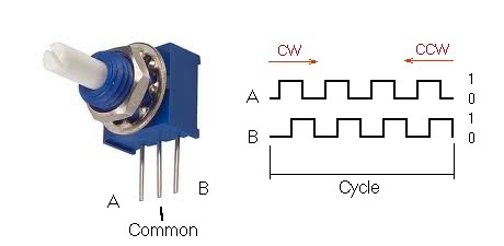
The total count of pulses per revolution gives as the encoder cycle.
The signals A and B are decoded by the software this way:
- Clockwise turn if a sequence of A(1)B(0), A(1)B(1), A(0)B(1) is detected.
- Counter clockwise turn if a sequence of A(0)B(1), A(1)B(1), A(1)B(0) is detected.
If the encoder is turning too fast, an invalid transition may occur, such as A(1)B(0) ->A(0)B(1) and there is no way to know which way the encoder turned. If the encoder is turning even faster, a backward count may occur.
To avoid invalid transitions I strongly recommend using encoders with a maximum of 16 pulses per revolution.
To improve
the performance of the encoders you can use the following setup: link
You will
get the best performance of the encoders and PSCockpit boards when configuring
the Main Board in “Expander Interrupt” mode. See this post: link
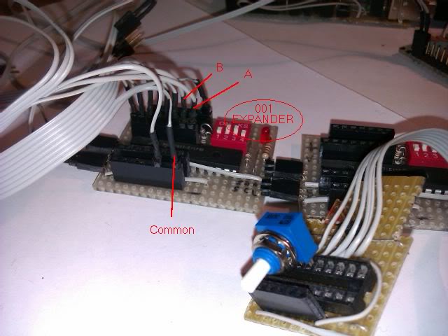
How to connect encoders to expanders
Just connect A y B pins to the inputs of the I/O expander and the common to ground. I have chosen in our example the expander 001, pins 0 and 1.
Let’s go to configure the encoder in the software:
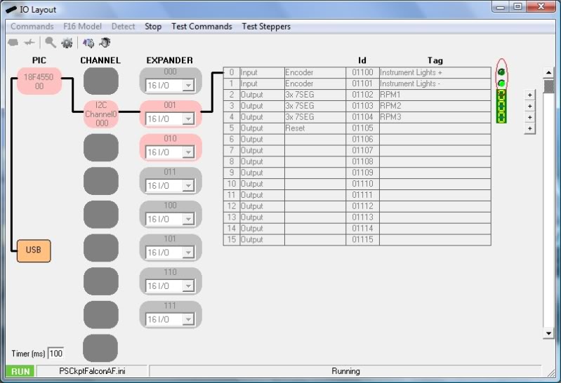
- Select IO Layout page.
- Select I2C Channel 001
- Select expander 001
- Select Input
- Select Encoder
- Set the tag you desire
- Accept
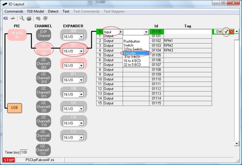
I have named this encoder as “Interior Light”.
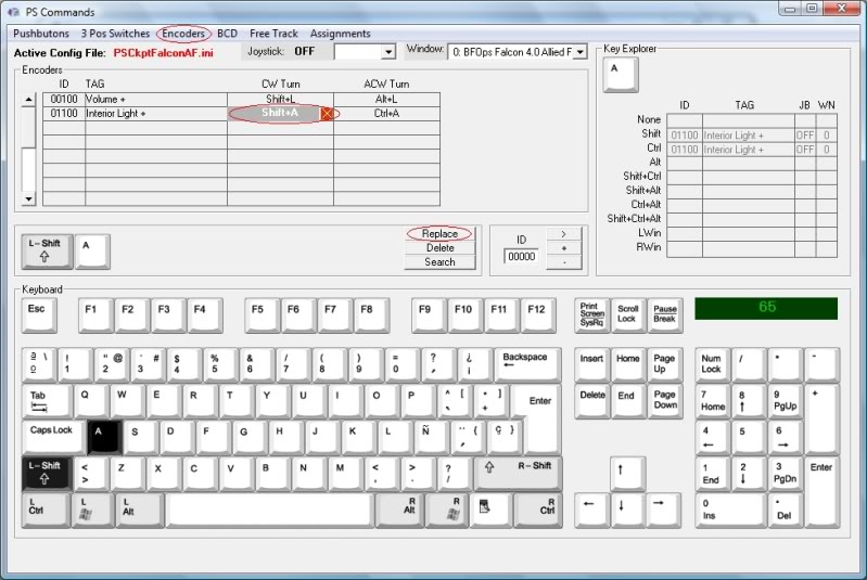
Now I will set the commands. I have selected the following callbacks in Falcon BMS:
- SimInteriorLightCW (turns the INT LIGHT knob clockwise) : Shift +A
- SimInteriorLightCCW (turns the INT LIGHT knob counterclockwise): Ctrl + A
Go to the PS Commands page and select “Encoders”. A list of all the encoders configured in the IO Layout page will appear. Select the “Interior Light” CW Turn field and press the key combination, in this case, “Shift + A”. Accept it by clicking on “Replace” and repeat the process for the CCW command.
Time to test it. In the I/O Layout page click on “Test” and you’ll see how the inputs of the encoder activate the simulated leds on the right as you turn the encoder clockwise or counter clockwise:
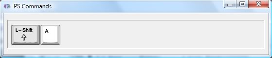
If you click on “Test Commands” a frame will appear where the key combination we have chosen are sent:
Assigning an encoder to a dimmer function
In a previous “how to” we have already seen how to set a dimmer function with a PWM signal coming out from the servos pins of the PS Cockpit System Main PCB.
To assign an encoder to the PWM signal we have to go to the F16 Model page and select Servos/PWM. In this page we have to select the desired servo/PWM in the Channel dropdown list and select “Dimmer” in the Magnitude dropdown list.
Now we can enter the encoder is going to drive the PWM signal clicking on the field “Encoder” and selecting the corresponding one in the dropdown list:
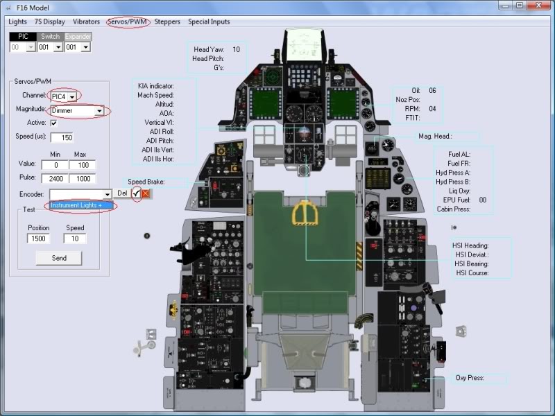
Don’t forget to click on the Active checkbox.
Now the encoder is tied to that PWM signal. We can also tell the software the amount of change we want by entering in the “Speed” field a quantity from 1 to 255. This is the quantity the software is going to add/subtract to the PWM signal. Less quantity means more encoder turns to get the full bright of the dimmer.
If the PWM signal goes down to a certain quantity then the dimmer will go OFF.
The data of the dimmers is stored by the software so at start up the dimmer will go to the same position it was when we exited the software. There is no need to adjust the encoder every time we enter the cockpit.
As the encoder will drive the PWM signal and will send the commands to the sim you will be dimming your cockpit and, at the same time, the lights of the sim. Just adjust your dimming speed to get in synchrony with the sim.
To test it we have to go back to the I/O Layout page, click on “Test” and activate “Test Commands”. The following video shows it working, sorry for the low quality.
Regards,
Shep
Just connect A y B pins to the inputs of the I/O expander and the common to ground. I have chosen in our example the expander 001, pins 0 and 1.
Let’s go to configure the encoder in the software:
- Select IO Layout page.
- Select I2C Channel 001
- Select expander 001
- Select Input
- Select Encoder
- Set the tag you desire
- Accept
I have named this encoder as “Interior Light”.
Now I will set the commands. I have selected the following callbacks in Falcon BMS:
- SimInteriorLightCW (turns the INT LIGHT knob clockwise) : Shift +A
- SimInteriorLightCCW (turns the INT LIGHT knob counterclockwise): Ctrl + A
Go to the PS Commands page and select “Encoders”. A list of all the encoders configured in the IO Layout page will appear. Select the “Interior Light” CW Turn field and press the key combination, in this case, “Shift + A”. Accept it by clicking on “Replace” and repeat the process for the CCW command.
Time to test it. In the I/O Layout page click on “Test” and you’ll see how the inputs of the encoder activate the simulated leds on the right as you turn the encoder clockwise or counter clockwise:
If you click on “Test Commands” a frame will appear where the key combination we have chosen are sent:
Assigning an encoder to a dimmer function
In a previous “how to” we have already seen how to set a dimmer function with a PWM signal coming out from the servos pins of the PS Cockpit System Main PCB.
To assign an encoder to the PWM signal we have to go to the F16 Model page and select Servos/PWM. In this page we have to select the desired servo/PWM in the Channel dropdown list and select “Dimmer” in the Magnitude dropdown list.
Now we can enter the encoder is going to drive the PWM signal clicking on the field “Encoder” and selecting the corresponding one in the dropdown list:
Don’t forget to click on the Active checkbox.
Now the encoder is tied to that PWM signal. We can also tell the software the amount of change we want by entering in the “Speed” field a quantity from 1 to 255. This is the quantity the software is going to add/subtract to the PWM signal. Less quantity means more encoder turns to get the full bright of the dimmer.
If the PWM signal goes down to a certain quantity then the dimmer will go OFF.
The data of the dimmers is stored by the software so at start up the dimmer will go to the same position it was when we exited the software. There is no need to adjust the encoder every time we enter the cockpit.
As the encoder will drive the PWM signal and will send the commands to the sim you will be dimming your cockpit and, at the same time, the lights of the sim. Just adjust your dimming speed to get in synchrony with the sim.
To test it we have to go back to the I/O Layout page, click on “Test” and activate “Test Commands”. The following video shows it working, sorry for the low quality.
Regards,
Shep
No comments:
Post a Comment