
-------------------------------------------------------------------------------------------------------------------------
For 11th Run displays see this post: v2 OLED display
-------------------------------------------------------------------------------------------------------------------------
The OLED display is supplied with a driver board attached to the display pcb. This driver board has a voltage regulator to convert the 5V to 3,3V, which supply power to the OLED display and two signal converters to convert 5V signals coming from the Main Pcb to 3,3V signals going to the display.
The OLED is configured to be used as 6800 Parallel 8 bit interface.
Before connecting the OLED display turn off the power supply of the Main Pcb and detach the USB cable from the computer.
Edited on Feb, 18th, 2014:
------------------------------------------------------------------------------------------------------------------------
Make a cable with 20 wire and connect straight pin to pin:
Be sure you have firmware version 1.5.0 or higher (1.5.1 recommended) in the Main PCB. You can see your firmware version by clicking on Help/About in the PSCockpit Software)
Make a cable with 14 wires and connect it from pin DBO to E.
Power the board directly from the power supply separately from the signals cable with SWG24 wires (thicker that the normal paralel strips used in PC connections).
------------------------------------------------------------------------------------------------------------------------
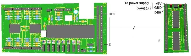
Not all the wires/pins are used for this display. If you want to make a cable with less wires, these are the pins used: +5V, GND, DB0, DB1, DB2, DB3, DB4, DB5, DB6, DB7, RST, R/W, Rs, and E.
Turn on power and connect the USB cable to your computer.
Run PSCockpit software and go to the LCD page and select the OLED display on the drop down list in the corresponding LCD tab. LCD 1 is used for the LCD connected to the most external connector of the Main Pcb and LCD 2 for the inner connector:
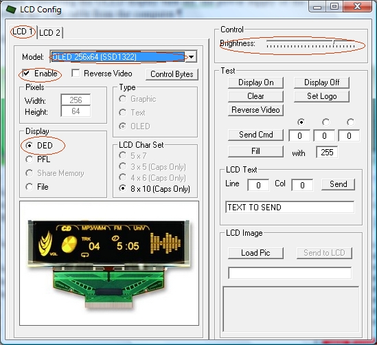
Don’t forget to check “Enable” and the “DED” or “PFL” to use with our sim and the desire brightness of the display with the slider bar.
In “Test” area you have some usual commands for you to try. They are self explanatory.
This display accepts 3 bytes commands. Select the corresponding option button above the commands text box to send one, two or three bytes.
You can also send monochrome bitmaps to the OLED but the horizontal length of the bitmap has to be multiple of 4.
NOTES:
* The OLED display is activated only when you enter PSCockpit software and is deactivated when you exit the program. This is to avoid image persistence on the OLED.
* The OLED display may be light sensitive. Caution should be taken to avoid exposure of this device to any light source during normal operation.
* The OLED display is not radiation protected.
Some pictures of the running OLED display:


Kind regards,
Shep
The OLED is configured to be used as 6800 Parallel 8 bit interface.
Before connecting the OLED display turn off the power supply of the Main Pcb and detach the USB cable from the computer.
Edited on Feb, 18th, 2014:
------------------------------------------------------------------------------------------------------------------------
Be sure you have firmware version 1.5.0 or higher (1.5.1 recommended) in the Main PCB. You can see your firmware version by clicking on Help/About in the PSCockpit Software)
Make a cable with 14 wires and connect it from pin DBO to E.
Power the board directly from the power supply separately from the signals cable with SWG24 wires (thicker that the normal paralel strips used in PC connections).
------------------------------------------------------------------------------------------------------------------------
Turn on power and connect the USB cable to your computer.
Run PSCockpit software and go to the LCD page and select the OLED display on the drop down list in the corresponding LCD tab. LCD 1 is used for the LCD connected to the most external connector of the Main Pcb and LCD 2 for the inner connector:
Don’t forget to check “Enable” and the “DED” or “PFL” to use with our sim and the desire brightness of the display with the slider bar.
In “Test” area you have some usual commands for you to try. They are self explanatory.
This display accepts 3 bytes commands. Select the corresponding option button above the commands text box to send one, two or three bytes.
You can also send monochrome bitmaps to the OLED but the horizontal length of the bitmap has to be multiple of 4.
NOTES:
* The OLED display is activated only when you enter PSCockpit software and is deactivated when you exit the program. This is to avoid image persistence on the OLED.
* The OLED display may be light sensitive. Caution should be taken to avoid exposure of this device to any light source during normal operation.
* The OLED display is not radiation protected.
Some pictures of the running OLED display:


Kind regards,
Shep