The new version V.0.9.7 of the PS Cockpit Software is available for download!!
PS Cockpit Software V.0.9.7 Changelog:
- Added UHF board and CP board self-configuration (IOLayOut)
- Added UHF Frequency and Channel internal values (Airplane Models)
- Added 0x7A and 0x78 addresses for OLED 1.3" (Adafruit OLED)
- Added On-line HOW TOs (General Settings)
- Added Quick Guide v3 (General Settings)
- Check Errors between Airplane Model and IOLayOut implemented (Airplane Models and IOLayOut)
- Added FTIT range value missing
- Corrected the bug of running the program while no Main Board is connected (window hook).
- CMDS functions on low chaffs and flares corrected
- CMDS works on SGL2016 displays as real
- Steppers X27 168 and X40 added. Only for low speed indicators with no different scales. (Airplane Models)
- Adafruit OLED 1.8" implemented (General Settings)
- Run time cycle improved
- Auto poll chip and I/O expander interrupt implemented (USB Timers)
You can download it at: Download
To update the firmware of the Main Board, visit: PS Cockpit Firmware Update
Thanks all for your patient!!!
Regards,
Shep

Sunday, April 5, 2015
PS Cockpit System F16 distribution file
You can download the F16 Cockpit Rev.1 distribution file in pdf format at:
http://www.mediafire.com/download/ww3sfnmyhtv1dhz/F16-PSCockpitDistribution.pdf
And the distribution list in excel format at:
http://www.mediafire.com/download/98x5860vpiykbbn/PSCockpitDistREV1.rar
Regards,
Shep
PS Cockpit Firmware Update
The new
firmware V 1.6.0 for the PS Cockpit Main Boards is available for download!!
PS Cockpit
System Firmware V.1.6.0 Changelog:
- Microchip
bootloader for W7&8 64 bits (4th Run Main Boards and later)
- PSCockpit
logo removed from the OLED displays- New RUN modes: Auto Poll and Expanders Interrupt
- Added control for Adafruit OLED 1.3" (SSD1306)
- Added control for steppers X27-168 and X40 double steppers
You can download
the firmware at: Download
Tools for
upgrading the firmware:
-
Users
of the PS Cockpit Main Boards of the 4th Run can update the
firmware in 64bits Windows operating system (These users do not need to update
the firmware by now) with PSFirmUpdtV2-4thRunMainBoards
- Users of the PS Cockpit Main Boards of previous runs can only update the firmware in 32 bits Windows operating systems PSFirmUpdtV1-PreviousMainBoards tool.
Do not try to update the firmware with the
incorrect tool version!!! It will ruin the firmware. If you have any doubt about your Main Board
tool please send me an email.
Regards,
ShepSaturday, April 4, 2015
HOW TO Poll the PS Cockpit Expanders
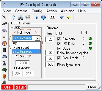
Since PS Cockpit Software V.0.9.7 and firmware version 1.6.0 you can poll the I/O expanders in three different ways:
- PC Mode: In this mode PC is responsible to check all the boards in a given cycle.
- Main Board: In this mode the Main Board will continuously poll the boards and send the values whenever they have changed. It will work better than the previous one.
- Expander Interrupt: In this mode the expanders 16 and 40 I/O expanders their self are responsible to check it one of their inputs have changed and they will ask the Main Board to read the I/O expander.
The selection of the mode can be done in the USB Timers Page of the PS Cockpit Software:
The interrupt inputs of the Main Board are as follows:
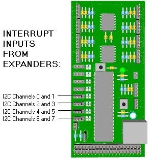
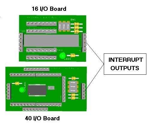
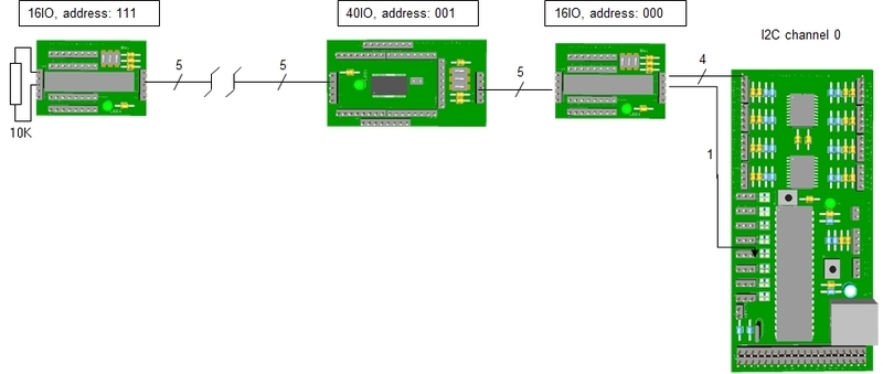
The interrupt outputs of the expanders are the middle pin of the I2C connector:
 As the interrupt outputs of the expanders are open drain active low outputs they need a pull-up resistor connected to 5V+. This can be easily accomplished by adding a 10K resistor to one of the expanders of the I2C daisy chain between the 5V+ pin and the interrupt pin:
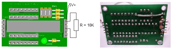
You will need to add this resistor at least to one expander of each I2C channels.
One I2C channel will be look at follows:
- PC Mode: In this mode PC is responsible to check all the boards in a given cycle.
- Main Board: In this mode the Main Board will continuously poll the boards and send the values whenever they have changed. It will work better than the previous one.
- Expander Interrupt: In this mode the expanders 16 and 40 I/O expanders their self are responsible to check it one of their inputs have changed and they will ask the Main Board to read the I/O expander.
The selection of the mode can be done in the USB Timers Page of the PS Cockpit Software:
The interrupt inputs of the Main Board are as follows:
The interrupt outputs of the expanders are the middle pin of the I2C connector:
You will need to add this resistor at least to one expander of each I2C channels.
One I2C channel will be look at follows:
HOW TO Use X27-168 and X40 Steppers
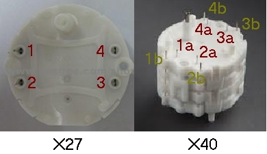
The X27 stepper motor is a miniature stepper developed primarily as an indicator drive for dashboard instrumentation and other indicator equipment. It has a "Lavet" type stepper motor and two step gear train which reduces the rotation by a factor of 180 whereby a full step driving pulse results in a one degree rotation of the pointer shaft.
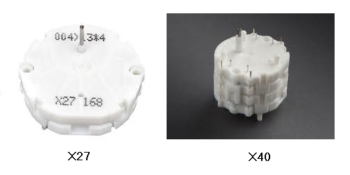
As the “Lavet” stepper motor needs 6 steps for a full rotation, one full rotation of the pointer shaft will need 1080 steps. Although this value is great for pointer resolution, the PS Cockpit System will not achieve the enough speed to drive the stepper motor for fast dials (i.e. Altimeter, FTIT, Rpm,…). In these cases Aircores motors are recommended.
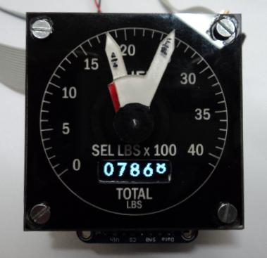
Nevertheless, the X-27 stepper motor can be used in the PS Cockpit System for slow rotating dials (EPU fuel, Cabin Press,…) and the X40, which is basically to X-27 stepper motors in a train with double shaft, can be used in the watch and fuel gauges:
The X27 stepper motors can be connected directly to the 16/40 I/O expanders of the PSCockpit system in 4 consecutive outputs as the maximum current draw of these steppers is 20mA. Of course, the X40 will need 4 more outputs for a total of 8.
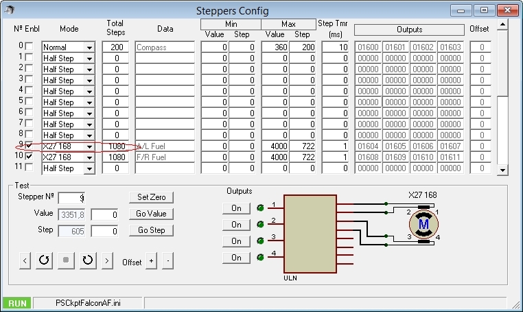
The configuration of the stepper motors in the PS Cockpit software is done in the same way as the unipolar stepper motors. See section “Configuring the stepper motor” in the following post:
PS Cockpit System - How to use steppers
The only difference is that “X27 168” has to be selected in the pull down list:
As the “Lavet” stepper motor needs 6 steps for a full rotation, one full rotation of the pointer shaft will need 1080 steps. Although this value is great for pointer resolution, the PS Cockpit System will not achieve the enough speed to drive the stepper motor for fast dials (i.e. Altimeter, FTIT, Rpm,…). In these cases Aircores motors are recommended.
Nevertheless, the X-27 stepper motor can be used in the PS Cockpit System for slow rotating dials (EPU fuel, Cabin Press,…) and the X40, which is basically to X-27 stepper motors in a train with double shaft, can be used in the watch and fuel gauges:
The X27 stepper motors can be connected directly to the 16/40 I/O expanders of the PSCockpit system in 4 consecutive outputs as the maximum current draw of these steppers is 20mA. Of course, the X40 will need 4 more outputs for a total of 8.
The configuration of the stepper motors in the PS Cockpit software is done in the same way as the unipolar stepper motors. See section “Configuring the stepper motor” in the following post:
PS Cockpit System - How to use steppers
The only difference is that “X27 168” has to be selected in the pull down list:
Edited on April 11th, 2016
-------------------------------------------------------------------------------------------------------------------------
Typical connection for X27 and X40 stepper motors are as follows:
Be aware that X27 and x40 stepper motors do not admit different scales so the gauge you want to drive needs to have the same scale in the full range.
-------------------------------------------------------------------------------------------------------------------------
Regards,
Shep
-------------------------------------------------------------------------------------------------------------------------
Typical connection for X27 and X40 stepper motors are as follows:
Please refer to your stepper motor datasheet for confirmation.
The connection between the stepper motor and the 16 I/O or 40 I/O expanders is straight forward: Select 4 consecutive outputs of the expander and connect them directly to 1 to 4 pins and avoid using outputs between two separate octo-inputs. This means that the four selected outputs have to be between 0-7, 8-15, 16-23, 24-31 or 32-39.
Be aware that X27 and x40 stepper motors do not admit different scales so the gauge you want to drive needs to have the same scale in the full range.
-------------------------------------------------------------------------------------------------------------------------
Regards,
Shep
HOW TO Configure the ICP panel (DEPRECATED)
Edited on April 11th, 2016
--------------------------------------------------------------------------------------------------------------------------
This panel has been deprecated. Use this HOW TO only if you have this ICP panel. Use ICP Rev1 instead: ICP Rev1
--------------------------------------------------------------------------------------------------------------------------
Digital I/Os
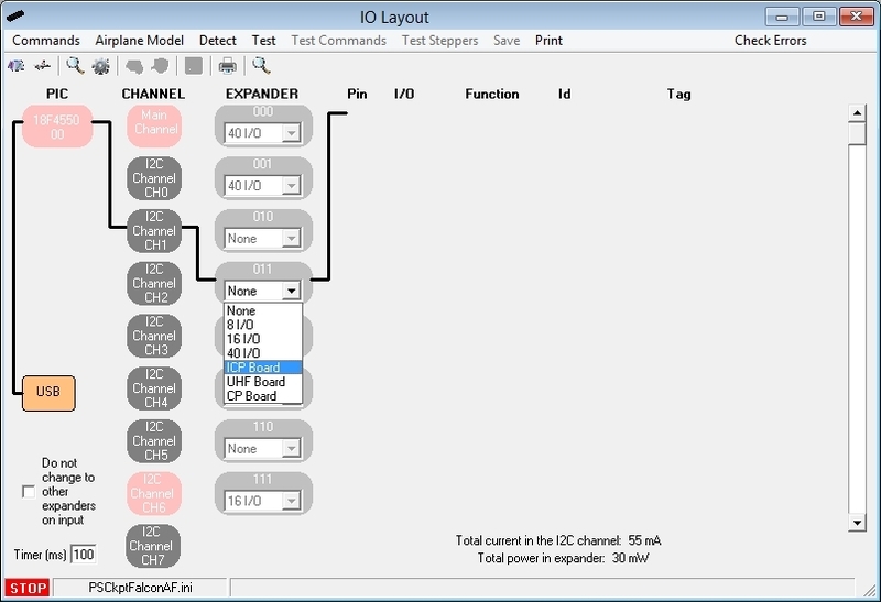
To configure the PS Cockpit ICP panel just select ICP Board from the Expander pull down list in the IOLayout page of the PS Cockpit Software at the correct I2C channel and expander configured in your ICP board (see PSCockpit Quick Guide V.3 – ICP PCB):
--------------------------------------------------------------------------------------------------------------------------
This panel has been deprecated. Use this HOW TO only if you have this ICP panel. Use ICP Rev1 instead: ICP Rev1
--------------------------------------------------------------------------------------------------------------------------
Digital I/Os
To configure the PS Cockpit ICP panel just select ICP Board from the Expander pull down list in the IOLayout page of the PS Cockpit Software at the correct I2C channel and expander configured in your ICP board (see PSCockpit Quick Guide V.3 – ICP PCB):
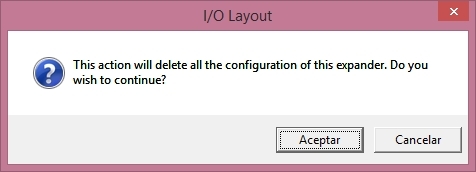
In case of there is some data already in the selected expander, the software will prompt you for continue:
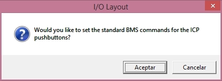
The software will also prompt you to add the standard BMS commands for the ICP:
Once the ICP panel is already configured you can modify the list of inputs/outputs as desire as well as the free I/O of the expander:
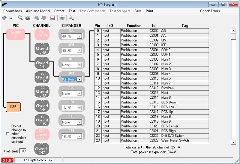
Be aware that once the configuration is saved, whenever you enter the IOLayout Page you won’t see “ICP Board” label on the expander anymore but the 40 I/O label.
Analogue inputs
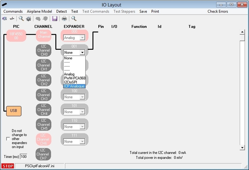
You have to repeat the process for the analogue inputs by selecting “ICP Analogue” in the I2C Main Channel:
Analogue inputs
You have to repeat the process for the analogue inputs by selecting “ICP Analogue” in the I2C Main Channel:
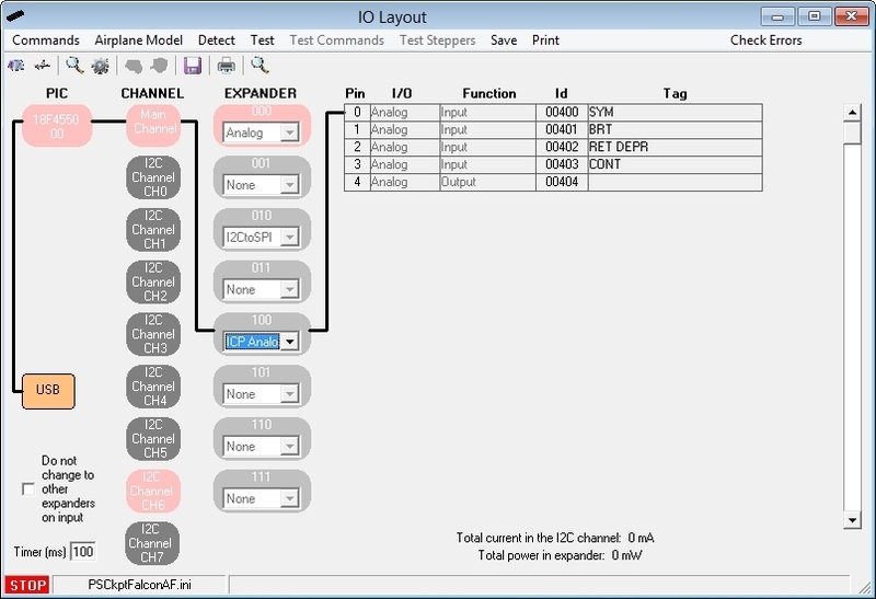
The expander will be configured as shown:
Friday, April 3, 2015
HOW TO Connect and Configure the Adafruit 1.3" OLED display (SSD1306)
The Adafruit 1.3” OLED display can be used in the PS Cockpit system for several functions as described before. The number of displays is limited to 5 and, depending on the number of them and their functions, they can have a high impact in the performance of the PS Cockpit System.
They can be connected to any of the I2C channels except the Main I2C Channel. As the address of the Adafruit can be selected by hardware, (2) Adafruit displays can be connected to the same I2C channel by selecting different address in each of them.
Follow this procedure to connect the Adafruit OLED display to the PS Cockpit System:
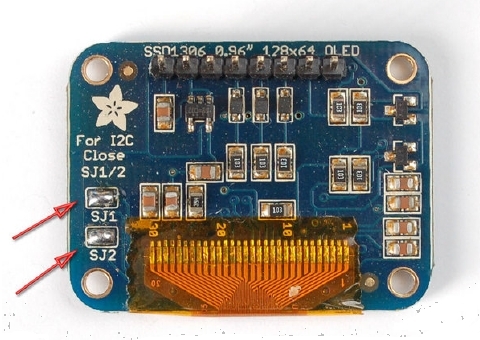
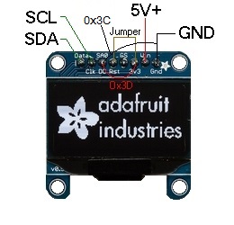
1. Prepare the Adafruit display for I2C operation by soldering the (2) jumpers SJ1 and SJ2 located in the back of the display:
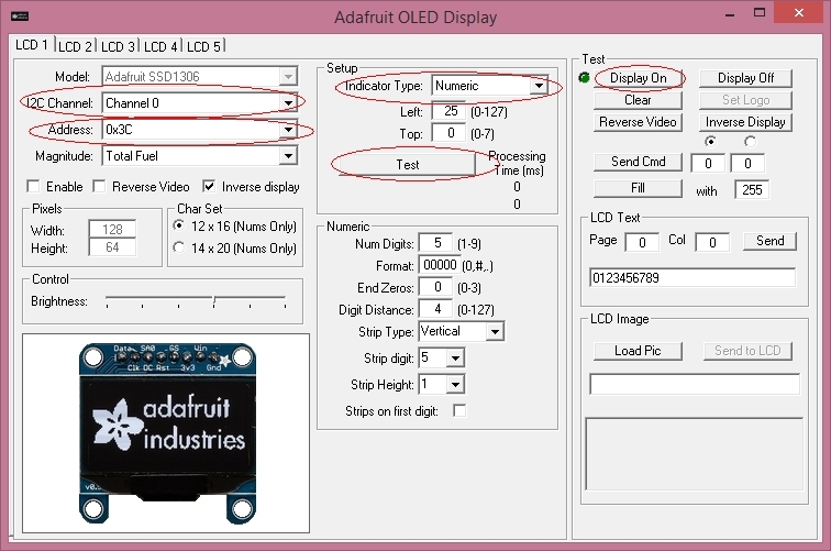
To configure the display follow the next procedure:
1. Select the I2C channel where the display is connencted.
2. Select the display address.
3. Select the Indicator Type in the Setup Frame
4. Click on “Display On”
5. Click on Test
They can be connected to any of the I2C channels except the Main I2C Channel. As the address of the Adafruit can be selected by hardware, (2) Adafruit displays can be connected to the same I2C channel by selecting different address in each of them.
Follow this procedure to connect the Adafruit OLED display to the PS Cockpit System:
1. Prepare the Adafruit display for I2C operation by soldering the (2) jumpers SJ1 and SJ2 located in the back of the display:
2. Supply power +5V to Vin pin and ground to GND pin.
3. Supply V+ to Reset pin. This can be easily done by wiring the 3.3V pin (output) to the Rst pin.
4. Select the Adafruit address mode by wiring the SA0 input:
- “0x3D” address: SA0 to 3,3V or 5V
- “0x3C” address: SA0 to GND
14/01/19 =========================================================
Some displays refuse working with address 0x3D. Tie SA0 to GND and use 0x3C address
Power the display OFF and power ON again, then config display.
================================================================
5. Connect the desire I2C channel of the PS Cockpit System to Data and Clock pins. It can be done from one of the expanders of the I2C channels.
Now that the Adafruit display is connected and powered you can run the PS Cockpit Software to configure it for the desired function by clicking on the Adafruit icon at the left of the Main Page.
3. Supply V+ to Reset pin. This can be easily done by wiring the 3.3V pin (output) to the Rst pin.
4. Select the Adafruit address mode by wiring the SA0 input:
- “0x3D” address: SA0 to 3,3V or 5V
- “0x3C” address: SA0 to GND
14/01/19 =========================================================
Some displays refuse working with address 0x3D. Tie SA0 to GND and use 0x3C address
Power the display OFF and power ON again, then config display.
================================================================
5. Connect the desire I2C channel of the PS Cockpit System to Data and Clock pins. It can be done from one of the expanders of the I2C channels.
To configure the display follow the next procedure:
1. Select the I2C channel where the display is connencted.
2. Select the display address.
3. Select the Indicator Type in the Setup Frame
4. Click on “Display On”
5. Click on Test
Indicator type
You can choose the function of the display by selecting one of the following types in the pull down menu: Numeric, Digital Watch, Tacan Channel, ILS Frequency, Picture or Level Strip.
Depending on the type selected some other related configurable parameters will appear.
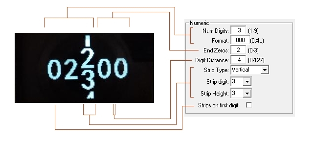
For Numeric, Digital Watch, Tacan Channel, ILS Frequency types, you can adjust the following parameters:
You can choose the function of the display by selecting one of the following types in the pull down menu: Numeric, Digital Watch, Tacan Channel, ILS Frequency, Picture or Level Strip.
Depending on the type selected some other related configurable parameters will appear.
For Numeric, Digital Watch, Tacan Channel, ILS Frequency types, you can adjust the following parameters:
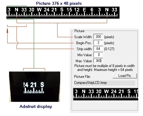
For Picture type you can adjust the following parameters:
The magnitude of the sim has to be selected in the pull down menu “Magnitude”
See some exmaples here
Regards,
Shep
The magnitude of the sim has to be selected in the pull down menu “Magnitude”
See some exmaples here
Regards,
Shep
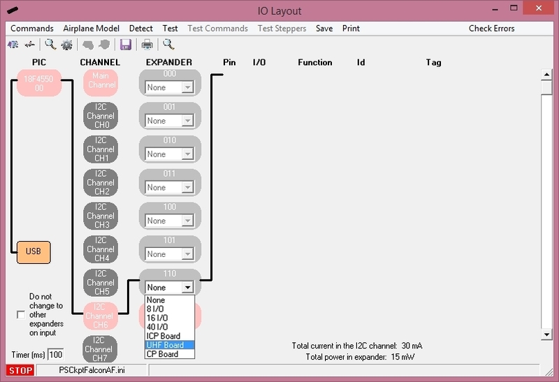
HOW TO Configure the UHF panel
For UHF Board description, options and how to configure the expander address, see PSCockpit Quick Guide V.4 – UHF PCB. You can access the Quick Guide from Help/Quick Guide menu in the PSCockpit software.
To configure the PS Cockpit UHF panel just select UHF Board from the Expander pull down list in the IOLayout page of the PS Cockpit Software at the correct I2C channel and expander configured in your UHF board:
Be aware that once the configuration is saved, whenever you enter the IOLayout Page you won’t see “UHF Board” label on the expander anymore but the 40 I/O label.
UHF Frequency and Channel internal values
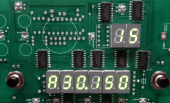
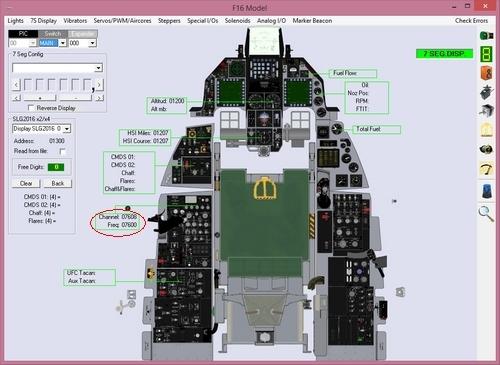
As BMS do not provide yet the values of the UHF Frequency and UHF Channel in the share memory area, you can choose to use the PS Cockpit Software internal values. This way, you will see the internal values of them displayed fancy in your UHF panel:
To configure the PS Cockpit UHF panel just select UHF Board from the Expander pull down list in the IOLayout page of the PS Cockpit Software at the correct I2C channel and expander configured in your UHF board:
In case of there is some data already in the selected expander, the software will prompt you for continue:
If you have the F16 Model Airplane, you will be prompted to:
- Set the standard BMS commands for the UHF board.
- Link the 7 segment displays to your Airplane model.
- Use internal values for UHF frequency and channel.
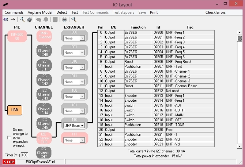
If you answer affirmative to the prompts, the UHF board will be ready to use and the F16 Model and Commands pages will show up with all the data already in the correct location:
Once the UHF panel is already configured you can modify the list of inputs/outputs as desire as well as the free I/O of the expander:- Set the standard BMS commands for the UHF board.
- Link the 7 segment displays to your Airplane model.
- Use internal values for UHF frequency and channel.
If you answer affirmative to the prompts, the UHF board will be ready to use and the F16 Model and Commands pages will show up with all the data already in the correct location:
Be aware that once the configuration is saved, whenever you enter the IOLayout Page you won’t see “UHF Board” label on the expander anymore but the 40 I/O label.
UHF Frequency and Channel internal values
As BMS do not provide yet the values of the UHF Frequency and UHF Channel in the share memory area, you can choose to use the PS Cockpit Software internal values. This way, you will see the internal values of them displayed fancy in your UHF panel:
This values will be modified with the encoders of the UHF panel accordingly.
To use this function open the F16 Model page, go to Special I/Os and select “Use UHF Internal Values” and fill the ID of the encoders in its location:
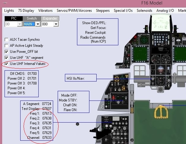
To use this function open the F16 Model page, go to Special I/Os and select “Use UHF Internal Values” and fill the ID of the encoders in its location:
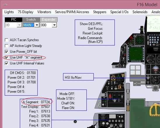
UHF “A” segment display
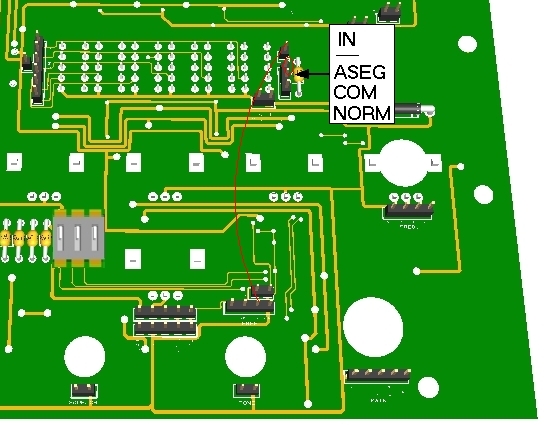
By default you UHF board is shipped with the first display of the UHF frequency in normal mode. This means that you will see standard numbers in the display. If you would like to see only “2”, “3” and “A” instead, you have to change the configuration of your board as follows:
1. Move the jumper to its original position COM-NORM to ASEG-COM.
2. Wire one free output from the board (by default output 24) with the IN pin of the connector.
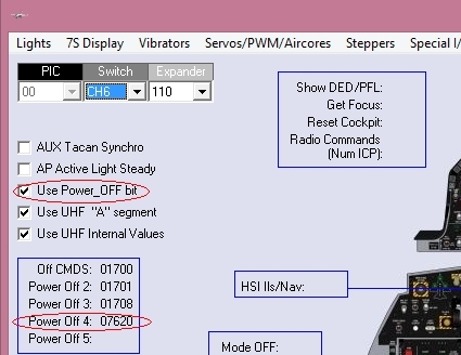
3. In the PS Cockpit Software, select “Use UHF “A” Segment” in the Special I/Os page of the F16 Model and add the output ID in its location:
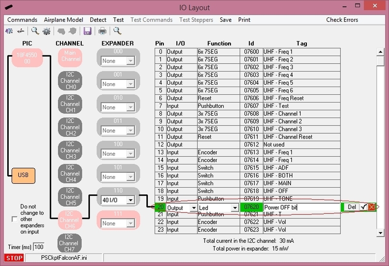
Power OFF bit
When the board is power ON, the 7 segments displays will display a value of (0). As with the 7 segment display boards, the displays can remain OFF until you energize the pit inside the simulator -as in the real life- using the Power OFF bit.
To use this function, follow the next procedure:
1. Detach the jumper from the Power OFF bit connector of the UHF board.
2. Wire a free output from the board to the left pin of the Power OFF connector (i.e. free output 20):
3. Select a Led Output for the output 20 in the IOLayout.When the board is power ON, the 7 segments displays will display a value of (0). As with the 7 segment display boards, the displays can remain OFF until you energize the pit inside the simulator -as in the real life- using the Power OFF bit.
To use this function, follow the next procedure:
1. Detach the jumper from the Power OFF bit connector of the UHF board.
2. Wire a free output from the board to the left pin of the Power OFF connector (i.e. free output 20):
4. Select “Use Power OFF bit” in the Special I/Os page of the F16 Model and add the output ID in one of the Power Off reserved locations:
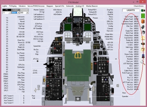
HOW TO Configure the Caution Panel
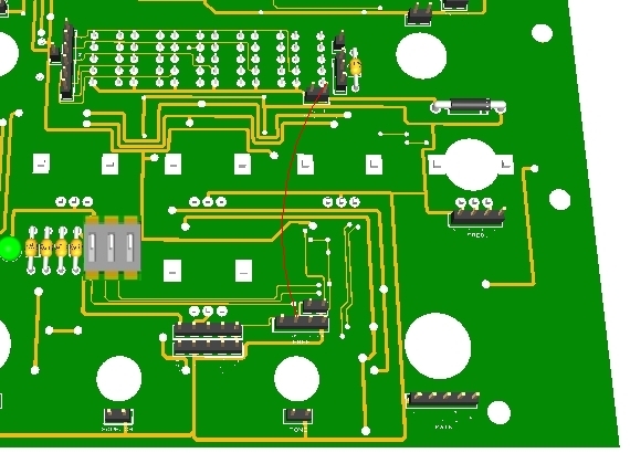
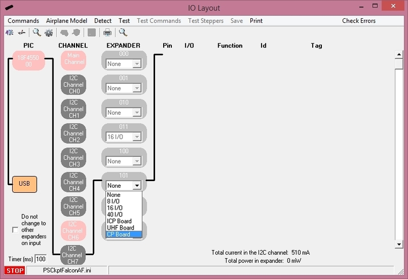
To configure the PS Cockpit Caution Panel just select CP Board from the Expander pull down list in the IOLayout page of the PS Cockpit Software at the correct I2C channel and expander configured in your Caution Panel board (see PSCockpit Quick Guide V.3 – Caution Panel PCB):
Regards,
Shep
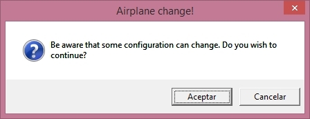
In case of there is some data already in the selected expander, the software will prompt you for continue:
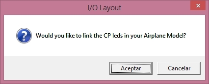
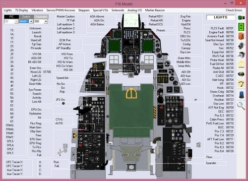
If you have the F16 Model Airplane, the software will prompt you to link the CP board to your Airplane Model:
The F16 Model will show up with all the data already in the correct location:
Once the Caution Panel is already configured you can modify the list of inputs/outputs as desire as well as the free I/O of the expander:
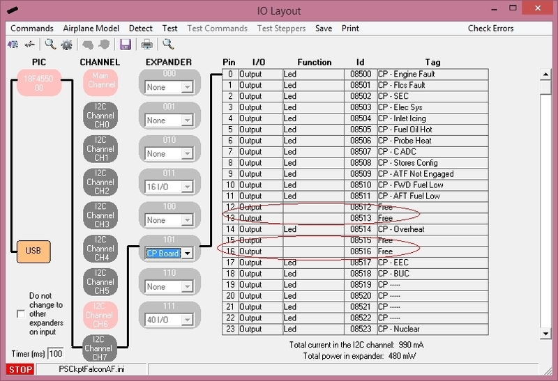
Be aware that once the configuration is saved, whenever you enter the IOLayout Page you won’t see “CP Board” label on the expander anymore but the 40 I/O label.Regards,
Shep
Airplane Models in the PS Cockpit System
At this
stage you should be familiar with the F16 Model Airplane configuration page in
the PS Cockpit Software where you can link your switches, leds and other
devices connected to your boards with the specific functions of the F16
Airplane Model. This linkage allows the PS Cockpit Software to know where are
the different elements when running you preferred simulator.
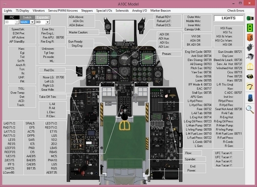
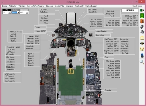
So far, other
two Airplane models have been implemented: A10C and F104G. You can change the
airplane model by clicking the desire option in the Airplane menu of the PS
Cockpit Software main page. The software will ask for confirmation:
Once you
have selected the Airplane Model, next time you click on the Airplane icon on
the left of the main page, the new Airplane Model will be displayed:
A10C Model:
Be aware
that although all three airplane models share some configuration data, the
function of some other data may change. Revise carefully the new
configuration!!!
When
changing the Airplane Model no data will be lost.
Regards,
Shep
HOW to Configure the Marker Beacon
The
PSCockpit allows you to program your Marker Beacon in two different ways: using
the data extracted from the sim or using the PSCockpit Marker Beacon.
Unfortunately
the state bit of this lamp can’t be extracted from the Flight Data to be used in
our cockpits.
PSCockpit Marker Beacon
The
PSCockpit Marker Beacon has been designed to use it when there is no such
information from the sim but some other data can be extracted. It can be use
for general aviation providing 3 coloured lights and 3 tones.
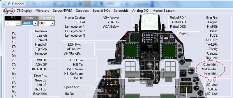
After
configuring 3 led outputs in the IOLayout of the PSCockpit Software, you have
to set these Ids in the F16 Model page of the PSCockpit System:
Marker Beacon in BMS
The F-16
has only one light as Marker Beacon and blinks at a different frequency according
to the marker you are overflying, but only outer (OM )
and inner marker (IM) are implemented in BMS.
In case your
favourite sim doesn’t have implemented the marker beacon, you can use the
PSCockpit Marker Beacon.
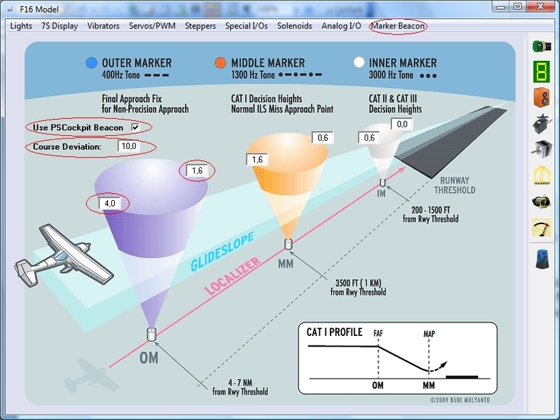
To do this,
you have to enter the parameters of the marker beacon in the Marker Beacon
option of the F16 Model page and select “Use PSCockpit Marker Beacon” checkbox.
You can
define the range of each marker from the runaway in nautical miles and the
deviation in degrees:
With the
marker ranges and the course deviation, the PSCockpit Software will activate
the marker beacon lights and the correspondent tone but only when the Tacan
Mode is set to ILS/NAV.
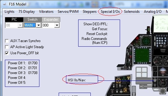
To tell the
PSCockpit Software that you are in ILS/NAV Tacan Mode goto Special I/Os of the
F16 Model page and select the input that will be active under the label HSI
ILS/NAV:
Regards,
Shep
Thursday, April 2, 2015
How to Interface 3 Positions Switches in the PScockpit Software
Select first the input and the 3 positions switch in the IOLayout page:
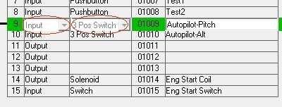
The
software will reserve 2 input for that switch.
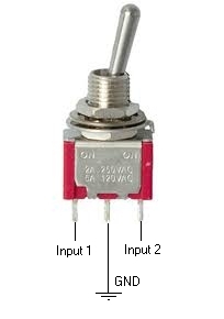
For wiring,
review your switch data sheet. Usually, the center pin is the common and you
have to wire it to ground. The other two pins have to be wired to the inputs:
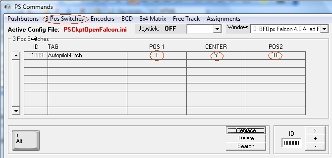
Now, go to
Commands Page of the PSCockpit Software and select 3 Pos Switches. You will see
the list of all 3 Pos. switches of the configuration. Select the desire one and
put the key combination you want to be sent to the sim. You will see 3 options:
when the position 1 is active, when the position 2 is active and when none of
them are active (Center):
Subscribe to:
Posts (Atom)