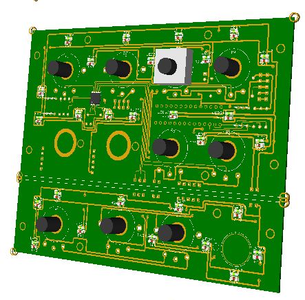
The board comes with the following elements:
- (1) 16 I/O chip to be connected to the digital I/O I2C channel of the PSCockpit system and its elements (resistors, connectors, …) to work with 5V
- (1) analogue chip to be connected to the Main Channel of the PSCockpit system and its elements (resistors, connectors, …) to work with 5V
- (4) potentiometers with ON/OFF switch
- (4) potentiometers
- (1) encoder
- (2) rotary switches
- (1) 3 position 12mm switch
- (27) SMD leds for lettering backlight.
The board has no free I/O’s.
You will find the following elements in the backside:
- (1) Connector for backlight illumination.
- (1) Connectors for digital I/O I2C channel.
- (1) Connectors for analogue Main Channel.
- (2) Mini-switch to select digital and analogue I2C channel addresses
To complete the AUDIO panel, you must add by yourself the front panel and knobs.
Be aware that this AUDIO panel does not fit perfectly the HISPAPANEL Audio1 and Audio2 panels. Some of the holes must be reworked although there is room in the board to do it without damaging any track.
Please check the dimensions of the AUDIO1 and AUDIO2 front panels at:
http://www.mediafire.com/file/sbzj6q4bb8j14x9/AUDIO1and2Panel-A3.pdf
Regards,
Shep
No comments:
Post a Comment