
The board comes with the following elements:
- (1) 16 I/O chip to be connected to the digital I/O I2C channel of the PSCockpit system and its elements (resistors, connectors, …) to work with 5V.
- (1) 3-positions switch with locking lever.
- (1) pushbutton.
- (9) SMD leds for indicators.
- (8 ) SMD leds for lettering backlight.
- (4) free I/O’s.
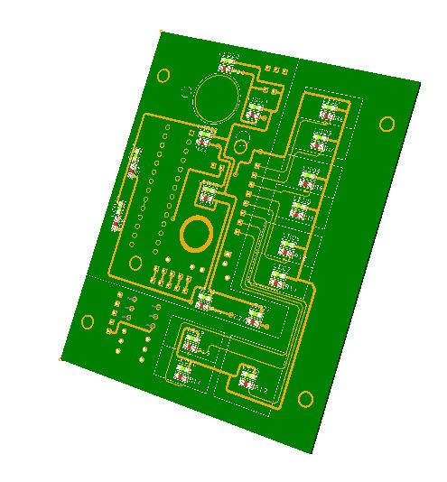
You will find the following elements in the backside:
- (1) Connector for backlight illumination.
- (1) Connectors for digital I/O I2C channel.
- (1) Mini-switch to select digital I2C channel address
- (1) Connector for 4 free digital I/O’s of the 16 I/O chip.
The board can be easily cut to use it with your own indicators using the existing inner connector for this purpose. If the indicators use another voltage than 5VDC you can attach the IO Enhancement pcb to light them.
To complete the ELEC panel, you must add by yourself the front panel, indicator caps and some separator to avoid the light going to other indicators.
Please check the dimensions of the ELEC front panel at:
http://www.mediafire.com/file/hqc9p4df4c27hf8/ELEC-A3.pdf
Regards,
Shep
No comments:
Post a Comment