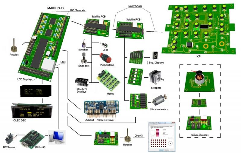
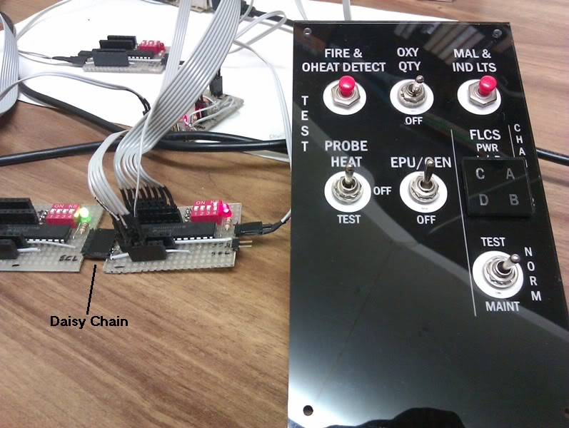
I have a new panel. It is the Test panel:

It has the following elements:
INPUTS:
- (2) pushbuttons: Fire & OHeat Detect and Mal & Ind Lts
- (2) switches: Oxy Qty and Epu/Gen
- (2) 3 position switches: Probe Heat and Test
The total inputs for these elements are: 1 per pushbutton + 1 per switch + 2 per 3posSwitch = 1 x 2 + 1 x 2 + 2 x 2 = 8 inputs
OUTPUTS:
- (4) leds: Flcs Pwr A, B, C, D
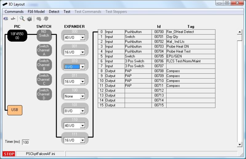
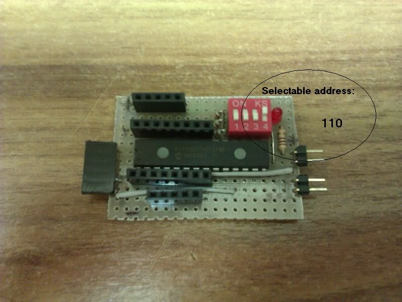
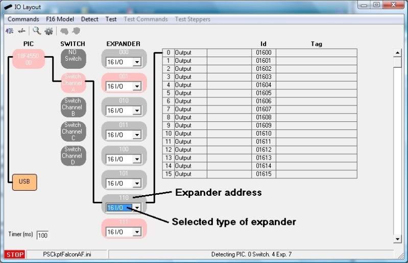
The total IO is 8 inputs + 4 outputs = 12 IO so I select the one expander of 16 IO and give it an unused address:
Now I wire all the elements of the panel…
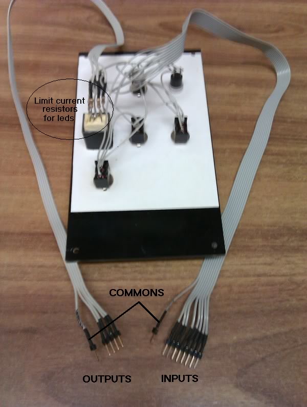
… and connect them to the selected expander:
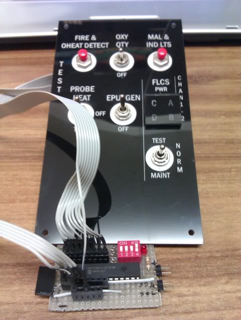
Now I connect the expander in daisy chain:
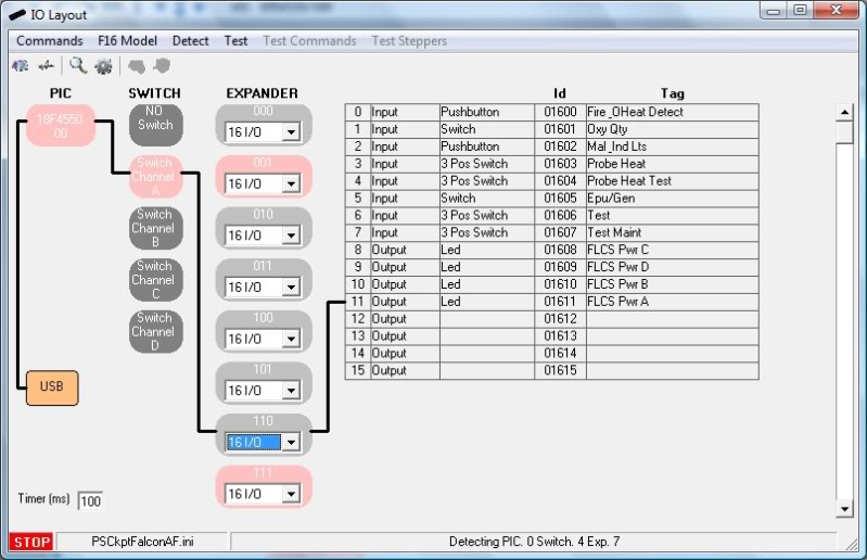
Next step: configure the expander in the software…

…for all the elements:
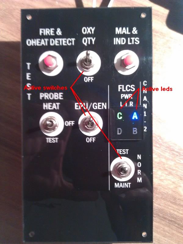
Now it’s time to test our new panel:

That’s all. Let’s see the results:
If we establish one fixed address of the expanders per panel then we all can use the same configuration and more important, if someone can supply individual panels with the elements already wired to the expander the end user could buy the ones he wants and they will be “plug and play” with no need of knowledge of electricity, electronics, program skills, nor configuration skills. Doesn’t seem exciting?

SIM INTERFACE
We have defined and tested the Test panel. Now we have to tell the software what to do with the inputs and what to do with the outputs.
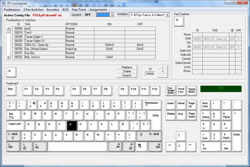
Inputs
Inputs are interfaced with the flight simulator through keystrokes. Every time the software detects any change of any of the inputs the system search the database to find the keystroke to be sent to the defined window.
We do that on the Command window following the next steps:
1. Select the type of input clicking on Pushbuttons
2. Find the desired input.
3. Select one of the 3 joystick DX buttons if you want the key combination be used in combination with the joystick. Select the window to send that key combination.
4. Select the desire input action.
5. Select the key combination.
6. Click on the Replace button and the key combination will be assigned.

Each type of input has the following actions to define a keystroke combination:
- Pushbuttons and Switches: ON/OFF.
- 3 Position Switches: POS1/CENTRE/POS2
- Encoders: CW/ CCW
- BCD: Matrix of all the available options for each type
Ok. Time to test!!!
Open the IO Layout window and:
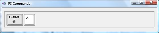
1. Click on Test Commands. PS Commands window will appear and the commands will be sent to it.
2. Activate the Epu/Gen switch
3. The key combination will appear on the PS Commands window.
- Pushbuttons and Switches: ON/OFF.
- 3 Position Switches: POS1/CENTRE/POS2
- Encoders: CW/ CCW
- BCD: Matrix of all the available options for each type
Ok. Time to test!!!
Open the IO Layout window and:
1. Click on Test Commands. PS Commands window will appear and the commands will be sent to it.
2. Activate the Epu/Gen switch
3. The key combination will appear on the PS Commands window.
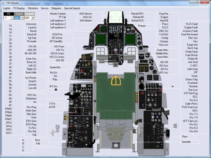
Outputs
As described above PSCockpit uses models to link the hardware with the software so you can use your cockpit with the different flight simulators as the software always knows where the outputs are.
All the lights, 7 segments displays, servos and steppers you can use have been defined in each model although they aren?t used by the flight simulator. This allows cockpit builders to wire and interface their entire cockpit so it can be used in the future whenever the functionality should be developed.
Only the F16 model has been developed so far but models can be defined by the users to be added on later versions.
In our Test panel we have 4 lights outputs, so we open the F16 model and:
1. Click on the Lights button
2. Select the switch and the expander the outputs have been wired to.
3. Click on the desire light and a drop down box will appear with all the outputs defined as leds in the IO Layout window.
4. Select the desire one.

Repeat the process for the 4 leds and check if everything is correct.As described above PSCockpit uses models to link the hardware with the software so you can use your cockpit with the different flight simulators as the software always knows where the outputs are.
All the lights, 7 segments displays, servos and steppers you can use have been defined in each model although they aren?t used by the flight simulator. This allows cockpit builders to wire and interface their entire cockpit so it can be used in the future whenever the functionality should be developed.
Only the F16 model has been developed so far but models can be defined by the users to be added on later versions.
In our Test panel we have 4 lights outputs, so we open the F16 model and:
1. Click on the Lights button
2. Select the switch and the expander the outputs have been wired to.
3. Click on the desire light and a drop down box will appear with all the outputs defined as leds in the IO Layout window.
4. Select the desire one.
You've got it!!!
Go to the main screen and run PSCockpit, run your preferred flight simulator and enjoy!!! PS Cockpit will extract the flight data from the flight simulator and will activate the corresponding outputs.
The flight simulators that PSCockpit works with, up to now, are the following:
- OpenFalcon
- Falcon AF
- Falcon BMS
- Microsoft Flight Simulator Series
- Lock On FC series
Other flight simulators on demand?..
Regards,
Shep