Time to launch a new year run of the PSCockpit System!!Those of you who don’t know yet how this system, please read the following links:
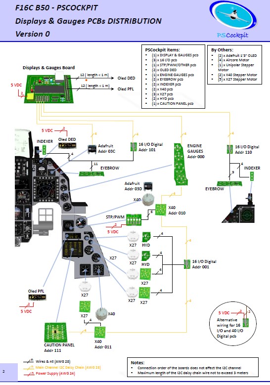
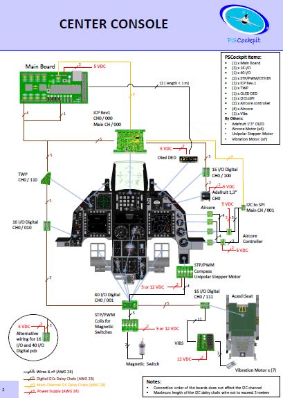
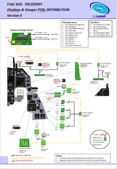
PS Cockpit System F16 distribution file for Main and Displays&Gauges boards:
https://psfalcon.blogspot.com/2026/03/f16c-b50-pscockpit-pcbs-distribution.htmlPSCockpit System:
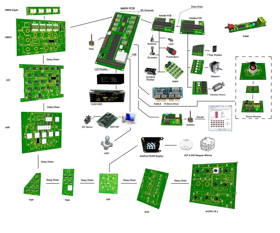
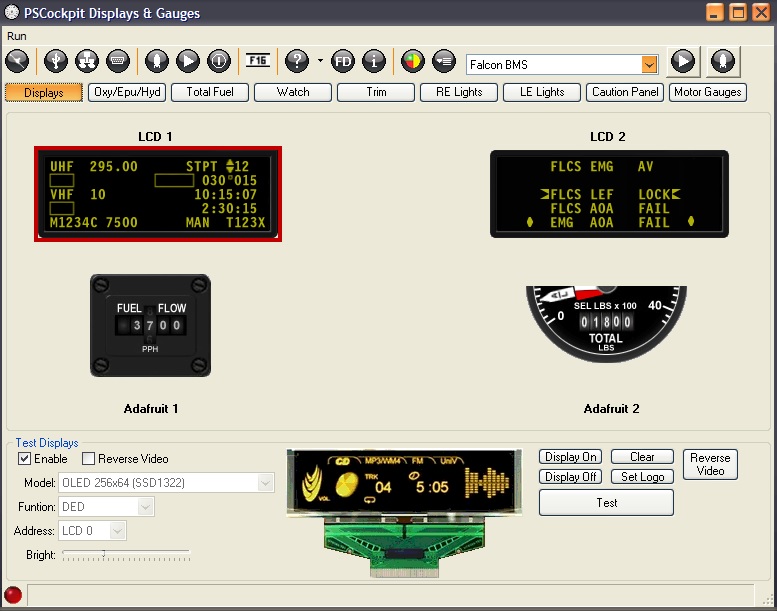
https://psfalcon.blogspot.com/2025/01/ps-cockpit-system-description.htmlPSCockpit Displays and Gauges:
https://psfalcon.blogspot.com/2025/01/pscockpit-displays-gauges-system.htmlMore information, downloads and guides at:
https://psfalcon.blogspot.com/2015/05/pscockpit-system-up-to-date-software.htmlThis Run features these new items:
• AUXCOMM pcb (100€)
The AUXCOMM board comes with the following elements:
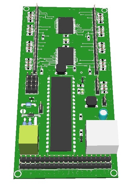
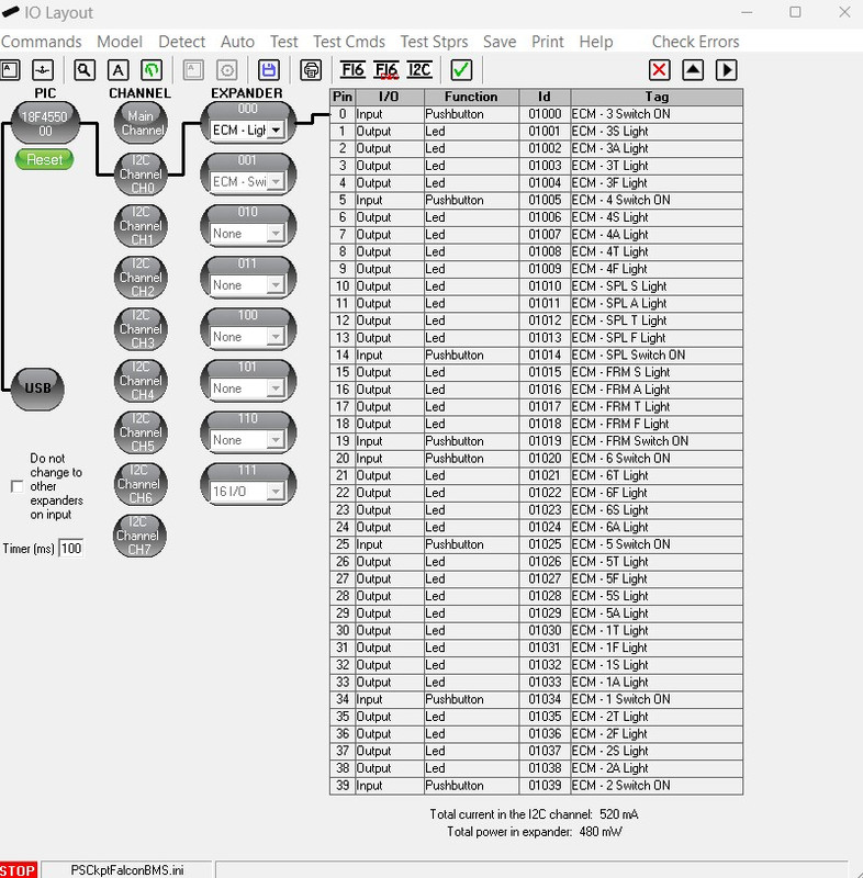
- (1) 40 I/O chip to be connected to the digital I/O I2C channel of the PSCockpit system and its elements (resistors, connectors, …) to work with 5V to drive the elements of the panel.
- (3) Toggle switches ON-OFF-ON for IFF REPLY, T/R and M4-Code.
- (1) Toggle switch ON-OFF for Monitor Audio.
- (8 ) Pushbuttons for Channel Selection.
- (1) OLED display for Channel Digits
- (1) PLA printed set of pieces to emulate Digilever channel selectors
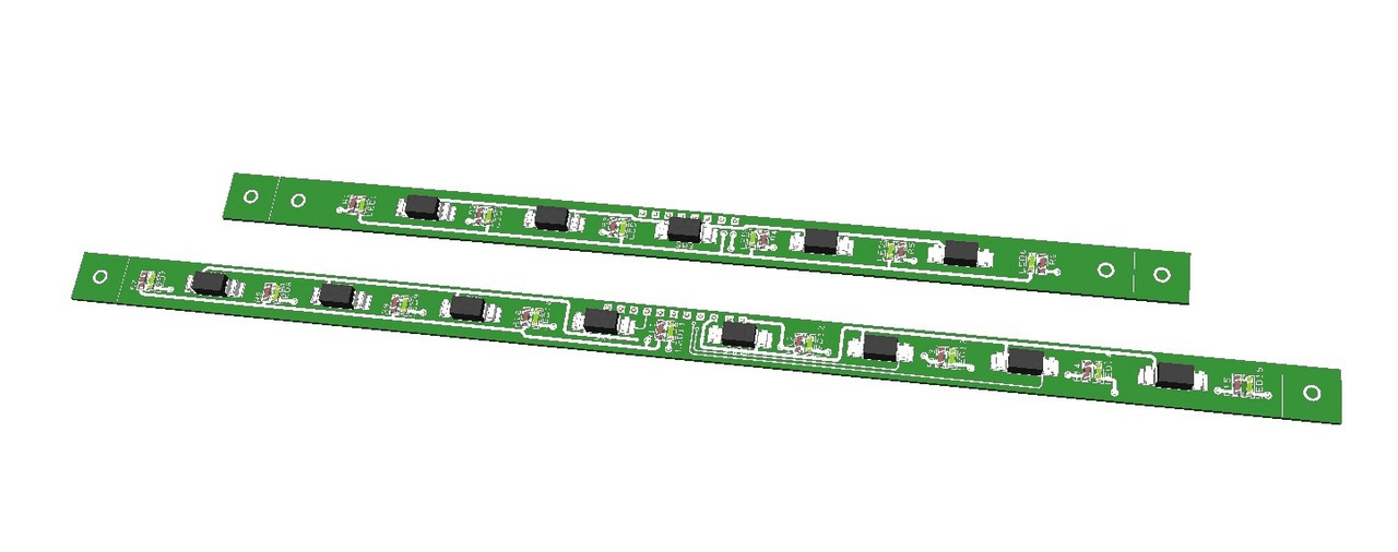
- (20) SMD leds for lettering backlight.
- (18) Free digital I/Os
You will find the following elements in the backside:
- (1) Connector for backlight illumination.
- (2) Connectors for digital I/O I2C channel.
- (2) Mini-switch to select 16I/O and 40I/O chips I2C channel addresses.
- (1) Connector for free digital I/Os.
You can use the free I/Os to connect your real Digilever channel selectors. In this case the PCB will be sent with no OLED display nor PLA printed set for a price of 60€.
To complete the AUXCOMM panel, you will need to add the following elements:
- AUXCOMM front panel
- AUXCOMM knobs
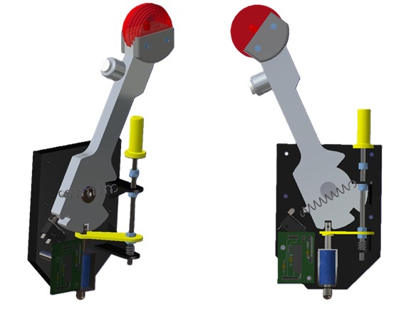
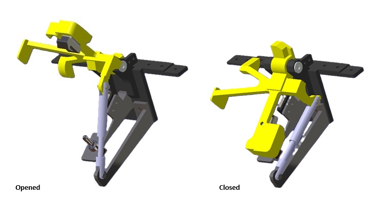
• Seat Ejection Handle (15€) 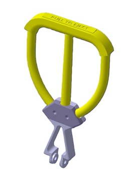
3D printed in grey PLA (base) and yellow flexible TPU (handle).
PSCockpit System Prices:The prices of PCB’s already mounted and tested are the following:
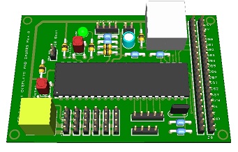
- Main Board V2 PCB: 80€
- Digital expander for 40 inputs/outputs: 33 €
- Digital expander 16 inputs/outputs: 10 €
- Steppers/Other voltage outputs pcb: 28 €
- 7 segment displays pcb for 6 displays: 18 €
- Analogue pcb for 4 inputs/ 1 output: 20 €
- I2CtoSPI pcb: 25€
- Aircore Controller pcb: 24€
- Aircore pcb: 15€
- Vibration motors pcb: 38€
- I/O Enhancement pcb: 6,5€
- Caution Panel board: 40€
- UHF board: 90€
- ICP pcb Rev 1: 90€
- CMDS board (with 2 rotary switches 30º & 45º, no toggles, no displays): 80€
- CMDS options:
- Miniature toggles 6 mm diam. (1 with locking lever): 50€
- SGL2016 displays Not available
- HDLG-1414 displays: At market price
- 7 segment displays pcb with 8 displays: 35€
- TWP board: 40€
- TWA board: 20€
- X40 stepper board: 20€
- PWM board: 20€
- ELEC board: 50€
- AUDIO1 & AUDIO2 board: 100€
- TRIM board: 80€
- TRIM INDICATOR board: 15€
- ECM pcb: 100 €
- CPD pcbs for one CPD: 90€
- EHSI pcb: 20 €
PSCockpit Displays&Gauges System Prices:The prices of the PCB’s already mounted and tested are the following:
- Displays & Gauges pcb: 55€
- X27 stepper pcb: 15€
- Eyebrow lights pcb: 15€
- Indexer pcb: 15€
- Engine Gauges for Aircores with electronics for PSCockpit System pcb: 90€
- Engine Gauges for X27 or Aircores without electronics: 65€
- Hyd pcb: 15€
3D Printed Components:- Gear Landing Set: 90€
- Canopy Spider Set: 20 €
- Shipments: 10€/ 18€ / 28€ depending on the total weight order and country
Time Line:- Orders and payments will be accepted until March. 29th. 2026
- Only direct bank transfers. Sorry for the inconvenience.
- Delivery: From May 2026
Thanks everybody for your support.
Shep