
Saturday, April 30, 2016
New PScockpit System Pcbs Distribution for the F16 Block 52
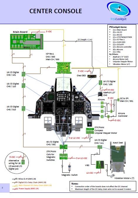
New PScockpit System pcbs distribution for the F16 Block 52, now in pdf format:
Sunday, April 17, 2016
PS Cockpit Software V.0.9.9 Update
The new version V.0.9.9 auto installable version of the PS Cockpit Software is available for download!!
PS Cockpit Software V.0.9.9 Changelog:
- JFS magnet driven by JET_FUEL_STARTED bit (BMS4.33)
- Added "software switch" function for analogue inputs (Commnands)
- Added "software encoder" fuction for analogue inputs (Commands)
- Added all the lights for TWA and TWP (F16 Model)
- Corrected the TWA and TWP lights to work as BMS 4.33 manual, including the flashing modes
- Corrected analogue bars when testing aircores (IOLayout)
- Added momentary coils for homemade magnetic switches (Airplane Models: Solenoids)
- Added speedbrakes solenoids (F16Model: Solenoids)
- Added UHF Off bit driven by OFF selector and COMM1 switch (Airplane Models: Special I/Os)
- Added CMDS pcb and ICP Rev1 pcb description (QuickGuideV4)
- Added warning on the IOLayout page about the issue that the stepper motors have to be connected in certain expander ranges (IOLayout)
- Changed overcurrent and overpower warnings to not consider expanders changed to "None" (IOLayout)
- Added Enter, Del, Escape, Page Up and Page Down keyboards inputs in the IOLayout for better eficiency (IOLayout)
- Added warning before going into RUN mode if the sim window name where to send commands hasn't been defined (PSCockpit)
- Removed warning when changing the sim and the airplane model is the same (PSCockpit)
- Added dropdown list with BMS callbacks. Now you can assign commands directly from the BMS callbacks with a left clik of the mouse on a given position in the list of switches, pushbuttons,.. (IOLayout)
You can download it at: Download
To update the firmware of the Main Board, visit: PS Cockpit Firmware Update
Thanks all for your patient!!!
Regards,
Shep
Monday, April 11, 2016
HOW TO Configure the CMDS Panel
For CMDS Board description, options and how to configure the expander address, see PSCockpit Quick Guide V.4 – CMDS PCB. You can access the Quick Guide from Help/Quick Guide menu in the PSCockpit software.
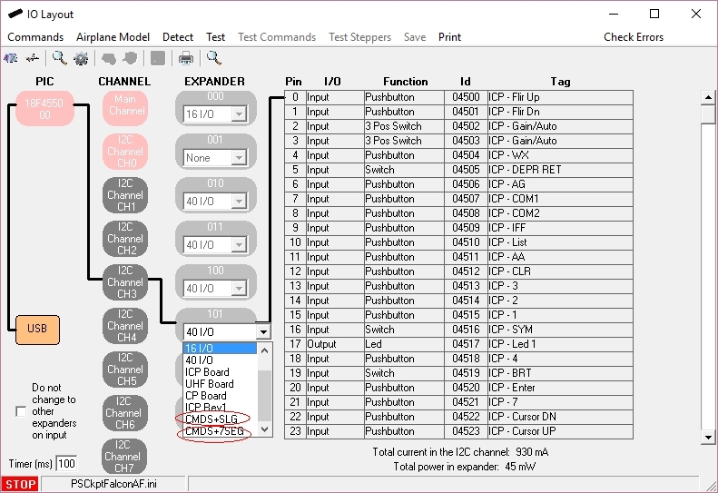
To configure the PSCockpit CMDS panel select the correct option from the Expander pull down list in the IOLayout page of the PS Cockpit Software at the correct I2C channel depending of your hardware:
- CMDS+SLG if you have SLG2016 displays in your CMDS pcb
- CMDS+7Seg if you have 7 segment displays in your CMDS pcb
In case of there is some data already in the selected expander, the software will prompt you for continue:

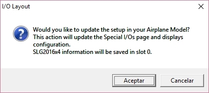
The software will prompt you to setup the SLG2016 or 7 segment displays in our Airplane model:
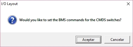
The software will also prompt you to add the standard BMS commands for the CMDS:
To configure the PSCockpit CMDS panel select the correct option from the Expander pull down list in the IOLayout page of the PS Cockpit Software at the correct I2C channel depending of your hardware:
- CMDS+SLG if you have SLG2016 displays in your CMDS pcb
- CMDS+7Seg if you have 7 segment displays in your CMDS pcb
The software will prompt you to setup the SLG2016 or 7 segment displays in our Airplane model:
The software will also prompt you to add the standard BMS commands for the CMDS:
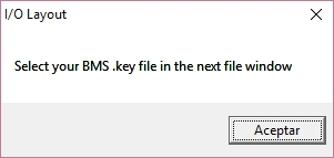
If you accept, the software will prompt you to search for your BMS .key file and will automatically search for the key strokes you have set in your .key file for the CMDS:
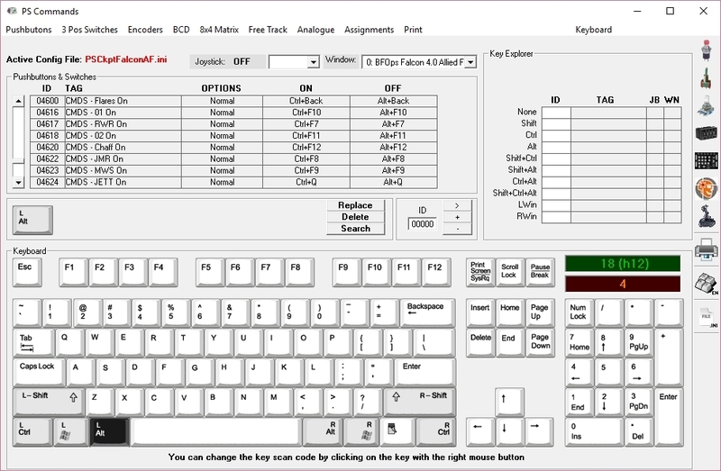
If any of the commands hasn't been set you will see a warning indicating how many commands haven't been set and the Commands page of the PSCockpit software will appear:
Once the CMDS panel is already configured you can modify the list of inputs/outputs as desire as well as the free I/O of the expander:

If any of the commands hasn't been set you will see a warning indicating how many commands haven't been set and the Commands page of the PSCockpit software will appear:
HOW TO Configure the ICP Rev1 Panel
For ICP Rev1 Board description, options, and how to configure the expander address, see PSCockpit Quick Guide V.4 – ICP REV1 PCB. You can access the Quick Guide from Help/Quick Guide menu in the PSCockpit software.
Digital I/Os
To configure the PS Cockpit ICP Rev1 panel just select ICP Rev1 Board from the Expander pull down list in the IOLayout page of the PS Cockpit Software at the correct I2C channel and expander configured in your ICP Rev1 board (see PSCockpit Quick Guide V.4 – ICP Rev 1 PCB):
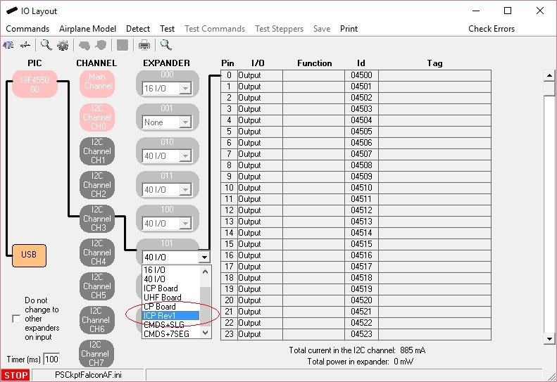
In case of there is some data already in the selected expander, the software will prompt you for continue:
If you accept, the software will prompt you to search for your BMS .key file and will automatically search for the key strokes you have set in your .key file for the ICP:
If any of the commands hasn't been set you will see a warning indicating how many commands haven't been set and the Commands page of the PSCockpit software will appear:
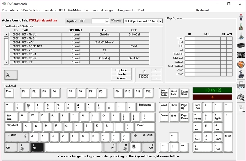
Once the ICP panel is already configured you can modify the list of inputs/outputs as desire as well as the free I/O of the expander:

Be aware that once the configuration is saved, whenever you enter the IOLayout Page you won’t see “ICP Rev1 Board” label on the expander anymore but the 40 I/O label.
Analogue inputs
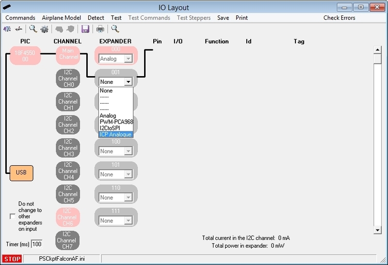
You have to repeat the process for the analogue inputs by selecting “ICP Analogue” in the I2C Main Channel:
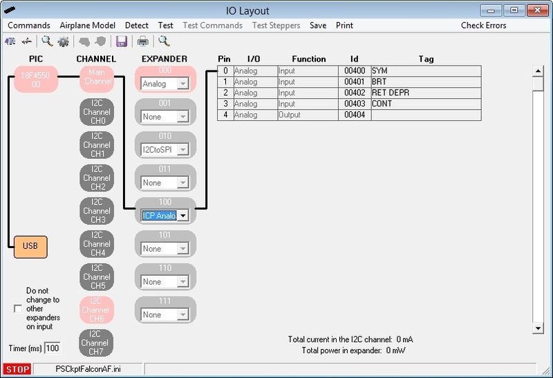
The expander will be configured as shown:
Digital I/Os
To configure the PS Cockpit ICP Rev1 panel just select ICP Rev1 Board from the Expander pull down list in the IOLayout page of the PS Cockpit Software at the correct I2C channel and expander configured in your ICP Rev1 board (see PSCockpit Quick Guide V.4 – ICP Rev 1 PCB):
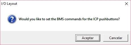
If you accept, the software will prompt you to search for your BMS .key file and will automatically search for the key strokes you have set in your .key file for the ICP:
Once the ICP panel is already configured you can modify the list of inputs/outputs as desire as well as the free I/O of the expander:
Be aware that once the configuration is saved, whenever you enter the IOLayout Page you won’t see “ICP Rev1 Board” label on the expander anymore but the 40 I/O label.
Analogue inputs
You have to repeat the process for the analogue inputs by selecting “ICP Analogue” in the I2C Main Channel:
The expander will be configured as shown:
Sunday, April 10, 2016
HOW TO Assing Keystrokes in PSCockpit System (COMMANDS)
One of the most important thing is how to interface the inputs of the cockpit (switches, encoders, BCD,...) with the sim. In the PSCockpit system, this interface is made by means of sending key strokes to the sim window once one input has changed its previous status.
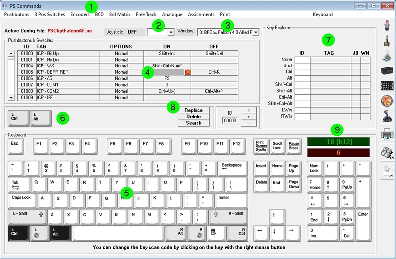
The key stroke sequence to be sent to the sim is defined in the Command page of the PSCockpit software. To set an specific command for each physical input element, follow this procedure:
You can change the keyboard to English/Spanish by clicking on Keyboard.
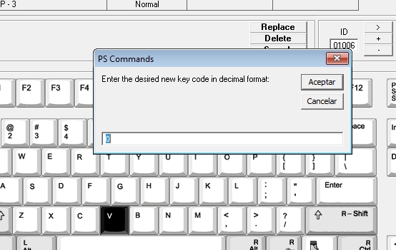
If you have another keyboard or the key is not working correctly in your sim, you can reassign the control code of the key by clicking on the desired key with the right button of the mouse. A box will appear asking for the new key code in decimal format:
For Falcon BMS sim users, the key file (.key) can be loaded by clicking on "BMS Key File".
You can read the procedure in the following post: HOW TO Assign Commands from Falcon BMS Key File
KEY STROKE OPTIONS
Some of the input devices have key stroke options. The explanation of those is the following:
Pushbutton and Switches:
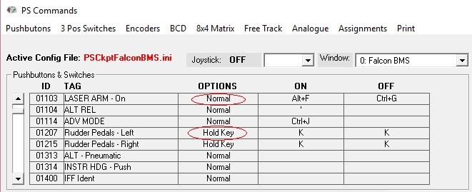
- Normal: Each time the input is activated the ON key stroke sequence is sent to the designated window. Each time the input is deactivated the OFF key stroke sequence is sent to the designated window.
- Hold key: The stoke sequence is sent continuously until the input is deactivated. You must stablish the same key stroke sequence in either ON and OFF fields.
3 Pos Switches:
- POS 1: When the 3 position switch is activated in position 1 the key stroke sequence is sent to the designated window.
- POS 2: When the 3 position switch is activated in position 2 the key stroke sequence is sent to the designated window.
- CENTER: When the 3 position switch is deactivated (center position) the key stroke sequence is sent to the designated window.

Encoders:
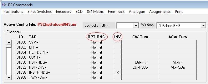
- Normal: When the encoder is rotated clockwise direction, the key stroke sequence under CW Turn will be sent to the designated window. Likewise, when the encoder is rotated counterclockwise direction the key stroke sequence under CCW Turn will be sent to the designated window
- Pulse: Reserved for future use.
- INV: When the INV tick is checked, the key stroke sequence sent to the designated window will be the opposite of the turning direction. This option allows to avoid rewiring of the encoder in case is reversed.
Analogue Inputs
When using pots in the PSCockpit system you can modify their behavior by selecting one of the following options:
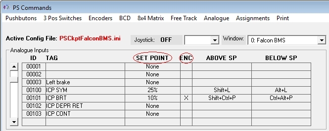
- SET POINT: By selecting a set point, a single key stroke sequence under Above SP will be sent to the designated window whenever the set point is bypassed by the analogue signal. Likewise, a single key stroke sequence will be sent to the designated window whenever the analogue signal goes under the stablished set point. The set point options are 5%, 10%, 25%, 50%, 75%, 90% and 95% of the analogue input total scale. This feature is useful to replicate by software the on/off switch functionality for pots with no such switch.
- ENC: By ticking the ENC check box, the pot will act as an encoder, sending the key stroke sequence under Above SP to the designated window each time the analogue signal bypass the amount in % established in the Set Point. Likewise, the Below SP key stroke signal will be sent to the designated windows whenever the analogue signal lower that amount in %.
Kind regards,
Shep
The key stroke sequence to be sent to the sim is defined in the Command page of the PSCockpit software. To set an specific command for each physical input element, follow this procedure:
- Select type of input element (pushbutton, switch, ...) by clicking in the upper menu.
- Select the joystick DX pushbutton in the dropdown list if you want to want to send a different key stroke combination while pressing the joystick button. If you want to send the key stroke combination without pressing any DX pushbutton of your joystick, select blank from the drop down list.
- Select the Window name of the application you want to send the key stroke combination to. To fill the name list of application windows read the following post: HOW TO Assign Key Strokes to Different Applications. Of course, the most important window name will be your favorite sim!.
- Select the position inside the matrix in which you want to place the key combination. A grey field will appear on that position.
- Select the key stroke combination by clicking on the keyboard or directly from your keyboard.
- The key stroke combination will appear in the middle frame.
- You can review in the Explorer frame if you have already assigned the key stroke.
- Click on "Replace" and the key combination will be transferred to the selected position of the matrix. If you click on "Delete" the key stroke combination will be deleted from the selected position of the matrix. If you click on "Search" the key combination will be searched in the matrix and if it is found in any position, it will be showed in the first line of the matrix.
- You can see the decimal and hexadecimal values of the key in the green frame and also the key codes for Falcon in the orange frame where you can copy by clicking on it.
If you have another keyboard or the key is not working correctly in your sim, you can reassign the control code of the key by clicking on the desired key with the right button of the mouse. A box will appear asking for the new key code in decimal format:
You can read the procedure in the following post: HOW TO Assign Commands from Falcon BMS Key File
KEY STROKE OPTIONS
Some of the input devices have key stroke options. The explanation of those is the following:
Pushbutton and Switches:
- Normal: Each time the input is activated the ON key stroke sequence is sent to the designated window. Each time the input is deactivated the OFF key stroke sequence is sent to the designated window.
- Hold key: The stoke sequence is sent continuously until the input is deactivated. You must stablish the same key stroke sequence in either ON and OFF fields.
3 Pos Switches:
- POS 1: When the 3 position switch is activated in position 1 the key stroke sequence is sent to the designated window.
- POS 2: When the 3 position switch is activated in position 2 the key stroke sequence is sent to the designated window.
- CENTER: When the 3 position switch is deactivated (center position) the key stroke sequence is sent to the designated window.
Encoders:
- Normal: When the encoder is rotated clockwise direction, the key stroke sequence under CW Turn will be sent to the designated window. Likewise, when the encoder is rotated counterclockwise direction the key stroke sequence under CCW Turn will be sent to the designated window
- Pulse: Reserved for future use.
- INV: When the INV tick is checked, the key stroke sequence sent to the designated window will be the opposite of the turning direction. This option allows to avoid rewiring of the encoder in case is reversed.
Analogue Inputs
When using pots in the PSCockpit system you can modify their behavior by selecting one of the following options:
- SET POINT: By selecting a set point, a single key stroke sequence under Above SP will be sent to the designated window whenever the set point is bypassed by the analogue signal. Likewise, a single key stroke sequence will be sent to the designated window whenever the analogue signal goes under the stablished set point. The set point options are 5%, 10%, 25%, 50%, 75%, 90% and 95% of the analogue input total scale. This feature is useful to replicate by software the on/off switch functionality for pots with no such switch.
- ENC: By ticking the ENC check box, the pot will act as an encoder, sending the key stroke sequence under Above SP to the designated window each time the analogue signal bypass the amount in % established in the Set Point. Likewise, the Below SP key stroke signal will be sent to the designated windows whenever the analogue signal lower that amount in %.
Kind regards,
Shep
Subscribe to:
Posts (Atom)