Sunday, November 17, 2013

PSCockpit Welcomes DCS A10C Supporters!!

A10C UFC BOARD


 Designed with (1) 40 I/O chip that can be connected to the digital I/O I2C channel of the PSCockpit system. It comes with corresponding elements (resistors, connectors, …) to work with 5V and a selectable mini-switch to select the desire I2C addresses.

For those of you that would like to use the Korry 318 "Caution" switch, the pcb is designed with room enough to make the cut-out of the switch and a connector to wire the switch.
Also included are the following components:
- (35) Mini switches with internal leds for pushbutton backlight. The leds are connected to the illumination circuit to allow “dimmering”.
- (21) SMD leds for lettering backlight.
- (1) frontal led

You will find the following elements in the backside:
- (1) Connector for backlight illumination.
- (1) Connector for digital I/O I2C channel,
- (1) Miniswitch to select digital I2C channel address
- (1) Connector for 5 free digital I/O of the 40 I/O board. You can use them to light the frontal led and/or to connect other switches, pushbuttons
- (1) One connector for the Korry 318 "Caution" switch

To complete the UFC you will have to add by yourself the following elements:
- UFC case
- Pushbutton covers

Please check the following dimensions for the UFC case.


You can download the file from:
http://www.mediafire.com/view/bujvl015hcd7e3q/UFCMetric.pdf

A10C CDU BOARD


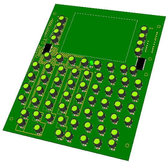
Designed with (2) 40 I/O chip that can be connected to the digital I/O I2C channel of the PSCockpit system. It comes with corresponding elements (resistors, connectors, …) to work with 5V and (2) selectable mini-switch to select the desire I2C addresses.

Also included are the following components:
- (66) Mini switches with internal leds for pushbutton backlight. The leds are connected to the illumination circuit to allow “dimmering”.
- (1) frontal led

You will find the following elements in the backside:
- (2) Connectors for backlight illumination.
- (2) Connector for digital I/O I2C channel in daisy chain
- (2) Miniswitchs to select digital I2C channel addresses
- (2) Connector for 10 free digital I/O of the 40 I/O boards. You can use them to light the frontal led and/or to connect other switches, pushbuttons

To complete the CDU you will have to add by yourself the following elements:
- CDU case
- Pushbutton covers.
- CDU display

Dimensions to follow.

Regards,
Shep

Sunday, November 3, 2013

HOW to Use POWER_OFF Bit

When you energize your pit with the PSCockpit Sytem, some others elements, like 7 segment displays, are also turned on, so, if you enter a mission in Ramp Start the displays will be showing zeros while the cockpit in the sim isn’t still energized.

To give more reality to our pits we can now take advantage of the POWER_OFF bit of the BMS sim (thanks BMS team!!).

You can activate this function by selecting the “Use Power_OFF bit” checkbox in the F-16 Model page under Special I/Os:


By selecting this function the PSCockpit Software will do the following:
- Remove any text in the DED and PFL display
- Activate all the POWER_OFF outputs of the F-16 Model (see picture above)
- More to come….

How to use the Power_OFF outputs in 7 Seg. Displays boards

To use this functionality with the 7 seg. displays boards, you will have to define, first, one output in the IOLayout. I have selected one of the 40 I/O board that I have in the CMDS panel to use it with the 7 seg. display board of the CMDS digits:


You will have to remove the jumper of the 7 Seg. Displays board and connect one wire from the pin marked as PWM to the selected output of the 40I/O board:


The last step is to select this output as one of the Power_OFF outputs in the F16 Model page (see first picture).

By the way, this PWM input of the 7 Seg. Displays Board can be connected to a PWM output to control the brightness of the displays.

(Added on Dec., 10th)

The Power Off bits have been updated for CMDS and UHF panels.
Now, this is the way PSCockpit works with the Power_Off Bits:


a) The “Use Power_OFF bits” checkbox (number 1), when checked, allows the software to use the Power Off bits (number 2), Inverted Power Off bits (number 3), OFF CMDS (number 5) and OFF UHF (number 6).

b) Power Off outputs (number 2) will be set to HIGH when the sim is in Power Off condition and Inverted Power Off outputs (number 3) will be set to LOW when the sim is in Power Off condition and vice versa when the sim is not in Power Off condition. Some devices will need a HIGH signal and some others may need a LOW signal.

c) The Power Off condition of the sim is an internal signal. In BMS, it comes from the Shared Memory, but, as some other sims (as old versions of BMS), do not have the internal Power OFF value, you can use the function with the Power Off switch of the Elec panel (number 4). This switch must be HIGH when Power Off condition.

d) There are specific Power OFF bits for the CMDS (number 5) and UHF panels (number 6) because some others conditions have been added as below explanations.

e) Off CMDS output (number 5) will be set to HIGH (display OFF) when one of the following inputs/signal are HIGH:
- In BMS: CMDS Off (from BMS Share Memory)
- In Falcon AF: Selector Mode OFF (number 9). Also in this sim, the rest of the inputs (number 10) are used for CMDS displays
- “Invert CMDS Off Bit” checkbox (number 12), when checked, inverts the output Off CMDS.

 f) Off UHF output (number 6) will be set to HIGH (display OFF) when one of the following inputs/signals are HIGH:
- Power Off (from BMS shared memory)
- UHF Selector Mode OFF (number 7)
- Selector COMM1 Off (number 8)
- All other values for UHF (number 11) are used only to use internal frequency. It is used in other sims where the frequency is not available.

Regards,
Shep