Friday, September 25, 2015

CMDS board


The new CMDS board has been designed with (1) 40 I/O chip to be connected to the digital I/O I2C channel of the PSCockpit system. It comes with corresponding elements (resistors, connectors, …) to work with 5V and two selectable mini-switches to select the desire I2C addresses. The board is prepared for 6 mm toggle switches but it has room to drill holes up to 12 mm diameter.

The following components are also inlcuded:
- (25) SMD leds for lettering backlight.
- (2) SMD leds for GO and NO GO indication.
- (3) SMD leds for DISPENSE READY indication
- (1) Rotary switch with 5 positions 45º
- (1) Rotary switch with 6 positions 30º
- Dimmer circuit for SLG2016 displays with a potentiometer of 10K. This pot comes apart so you can locate it in any other place of your pit.

You will find the following elements in the backside:
- (1) Connector for backlight illumination.
- (1) Connector for digital I/O I2C channel,
- (1) Miniswitch to select digital I2C channel address
- (1) Connector for7 free digital I/Os of the 40 I/O board.
- (1) Selectable connector for dimmer/CMDS_OFF bit

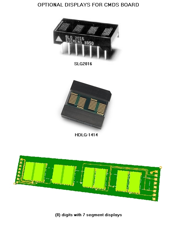
To complete the CMDS board, it can be supplied with the optional following elements:
- (8)Mini Toggle ON-OFF switches of 6 mm diameter. One of them comes with a locking lever for the JETT switch. Be aware that these switches are smaller than the real ones.
- SLG2016 displays, or
- HDGL-1414 displays, or
- 7 Segment display board with 8 digits of 4.22 x 7.62 mm


If you select the CMDS board with the switches and one of the displays options you will only have to add by yourself the CMDS case and the PRGM and MODE knobs for the rotary switches.

Please check the dimensions for the CMDS case at:
Link

Regards,
Shep

ICP BOARD Rev1


The new ICP Rev.1 board has been designed with (1) 40 I/O chip and (1) analogue chip that can be connected to the digital I/O I2C channel and the I2C analogue channel of the PSCockpit system. It comes with corresponding elements (resistors, connectors, …) to work with 5V and two selectable mini-switches to select the desire I2C addresses.

Also included are the following components:
- (23) Mini switches with internal leds for pushbutton backlight. The leds are connected to the backlight circuit to allow “dimmering”.
- (16) SMD leds for lettering backlight.
- (1) Mini joystick. The board has been carefully designed so you can remove the mini joystick, drill the board and place you own joystick
- (3) frontal leds
- (2) Mini-toggle switches Drift C/O and Gain. You can remove this toggle switches, drill the board up to 14mm.diam and place you own toggle switches.
- (4) 100K pots for side wheels with ON/OFF switch. These pots can be removed and changed with encoders.

You will find the following elements in the backside:
- (1) Connector for backlight illumination.
- (1) Connector for digital I/O I2C channel,
- (1) Connector for analogue I2C channel
- (1) Miniswitch to select digital I2C channel address
- (1) Miniswitch to select analogue I2C channel address
- (1) Connector for1 free digital I/O of the 40 I/O board.

To complete the ICP you will have to add by yourself the following elements:
- IPC case and pushbuttons
- Side wheels. As the pots are in the backside of the board the recommended wheel diameter is 44mm

Please check the following dimensions for the ICP case: http://www.mediafire.com/download/z4972pne2vhjcc0/IPCRev1-A3.pdf

Regards,
Shep

Tuesday, September 22, 2015

PSCockpit System 5th Run

Time to launch a new run of the PSCockit System!!  :thumbsup:
In this run the following new boards have been developed:

- ICP pcb, revision 1.
- CMDS pcb
- CMDS 7 segment display digits


PSCockpit System 5th Run!!!


Description
- One stop hardware and software for cockpit systems. Once the cockpit is connected you can configure the software individually for each sim.
- Easy configuration and setup for people with out electronic knowledge.
- Avoid excessive wiring runs along the cockpit.
The system uses small satellite PCB’s that can be distributed along the cockpit. The communication between these satellite PCB’s and the Main PCB is done with only 2 wires (I2C protocol) plus the power cables. These wires can be connected in daisy chain. The idea is to wire each of the cockpit panels to only one satellite PCB.

More information, downloads and guides at http://psfalcon.blogspot.com.es/2015/05/pscockpit-system-up-to-date-software.html

Pricing and ordering information at:
http://www.viperpits.org/smf/index.php/topic,10254.0.HTML


Regards,
Shep