Thursday, December 29, 2022

PSCockpit Runtime and Timers

To improve the runability of PSCockpit with your favorite simulator you will need at sometime to deal with PSCockpit timers. The functionality of the timers is described below.

You can access the Runtime and Timers by clicking on “USB Timers”:
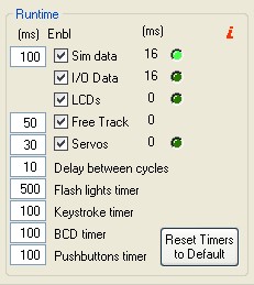


Sim Data Timer

The first timer is the Sim Data Timer and controls the Sim Data, I/O Data and LCDs routines where the following operations are made:

  • Sim data: the data is read from the simulator.
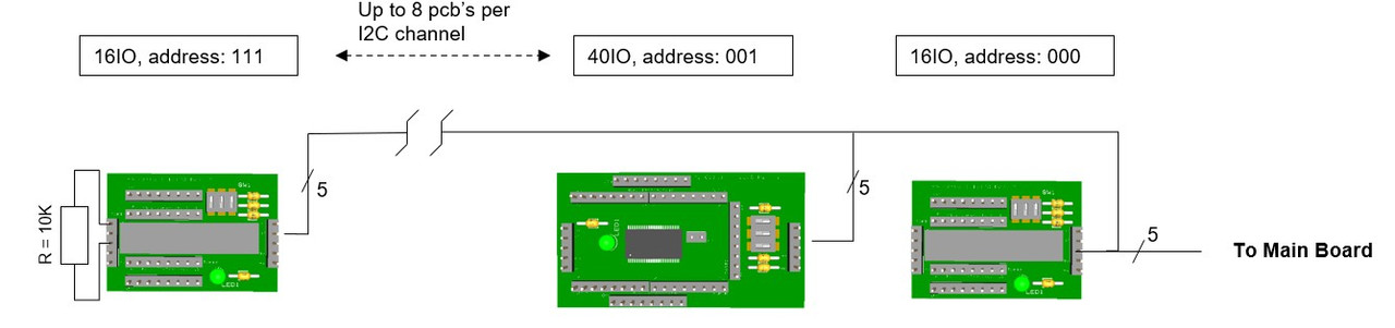
  • I/O Data: if the expanders aren’t polled in “Exp. Interrupt” mode, the inputs from the pcb’s are read and the commands are sent to the simulator. Then, the outputs of the pcb’s are set. if the expanders are polled in “Exp. Interrupt” mode, the commands are sent as soon as they are received from the Main Board.
  • LCD`s: the data of the LCD’s is sent to the Main Board.
With the checkboxes under the column “Enbl” you can tell the program to skip one of the above subroutines. The checkboxes values are not saved in the configuration file, and they will show up as checked as soon as you run PSCockpit again. They are only valid for troubleshooting purposed as described below.

The third column shows the time in milliseconds that the program takes to complete each subroutine and the led indication shows in which subroutine the program is.

The elapsed time showed beside Sim Data is the total time to complete a cycle and includes the subroutine times and the delay between cycles.

In case you are suffering any delay retrieving data from the simulator or from your pcb’s, you can check what routine is taken the most time to complete and deactivate it to review the behavior of all the other subroutines.

Free Track Timer

This timer controls the time the subroutine is ran to get the data from the Free Track. Free Track in PSCockpit is used to control the projector movement and/or the side views of your simulator. In this way, you can configure when to change to a certain view in your simulator depending on the Free Track data. Unchecking this checkbox avoid the program to enter the subroutine but does not deactivate the use of Free Track. If you want to deactivate Free Track, enter Free Track page and uncheck “Use Free Track Data” checkbox in that page.

The third column shows the time in milliseconds that the program takes to complete this subroutine.

Servos Data

This timer controls the refreshing time of the gauges driven by servos, aircores and/or steppers. Be aware that, even if you set this timer to 0, the gauges won’t move until the data of the sim is read, which is controlled by the Sim Data timer. Thus, this timer shouldn’t be lower than the Sim Data Timer.

For troubleshooting purposes, you can tell the program to skip this subroutine by unchecking the “Enbl” checkbox. The checkbox value is not saved in the configuration file, and it will show up as checked as soon as you run PSCockpit again.

The third column shows the time in milliseconds that the program takes to complete this subroutine and the led indication shows when the program is running it.

Delay Between Cycles

This timer controls the time to run another cycle. This time is needed to setup some configurations internals as the 8x4 matrix cycle.

Flash Lights Timer

This timer controls the time of flashing for the outputs configured as “Flash Leds” in the IO Layout.

Keystrokes Timer

PSCockpit sends the commands to your simulator by means of virtual keystrokes. This timer controls the time that the virtual keystrokes are held as pushed. Some of the tested sims doesn’t react when sending a simple tick of a key combination. If this is the case, increase this timer until the sim react to your commands.

BCD Timer

When using BCD combinations, the diodes and electronics need some setup time. This timer controls the time from the physical action of pushing a pushbutton of a BCD matrix and the reading time of PSCockpit. Thus, this timer avoids phantom inputs as well as wrong commands sent to the simulator. Be aware that you will need to hold down the pushbutton all the amount of time set in this timer for PSCockpit to react.

Pushbuttons Timer

As well as the BCD timer, this timer controls the time from the physical action of pushing a single pushbutton and the reading time of PSCockpit. Thus, this timer avoids phantom inputs as well as wrong commands sent to the simulator. Be aware that you will need to hold down the pushbutton all the amount of time set in this timer for PSCockpit to react.

Reset Timers to Default

Self-explanatory.

High Elapsed Time symptom’s

If any of the elapsed times are much higher than expected, it can be a symptom of a bad configuration of PSCockpit system. Some of them are as follows:
  • High Sim Data elapsed time: Check the I/O Data elapsed time and the LCD’s elapsed time. If any of these show high values, disable the affected subroutine by unchecking the corresponding check box and watch the effect on this elapsed time. High elapsed times of this timer alone reflects a communication problem with the sim. It may be caused of wrong versions of PSCockpit and/or the sim. Low PC specs can cause this symptom also.
  • High I/O Data elapsed time: This is normally caused by a wrong configuration of a pcb, a faulty pcb, or a misconfiguration of one pcb. Review your I/O Layout and test your pcb’s one by one to detect any faulty one.
  • High LCD’s elapsed time: This is normally caused of a wrong configuration of a faulty LCD or Adafruit OLED. Review your LCD`s configuration and Adafruit OLED configurations and test one by one by disabling all the others displays. This operation can be accomplished by unchecking the “Enable” checkbox for each display in the “LCD” and “Adafruit OLED” pages.
  • High I/O Data and LCD’s elapsed times: This is a symptom of problems in the USB connector/cable or USB drivers. Check the troubleshooting guide here: link
  • High Servos Data elapsed time: This is normally caused of a wrong configuration of a faulty servo, Aircore or stepper motor. Review your gauges configuration on “Gauges” and “Stepper Motors” pages and test one by one by disabling all the other gauges by unchecking the “Enable” checkbox for each gauge.
Regards,
Shep


Tuesday, August 23, 2022

PSCockpit Main Board Troubleshooting Guide

GENERAL CONSIDERATIONS

To properly run the Main Board, take in account these general considerations:
  • Run PSCockpit software with Admin rights.
  • Close PSCockpit software, disconnect the USB cable from the PC and turn off the Main Board and wait a few seconds in every test. If there is a leakage in any board, the Main Board chip can go to sleep mode in case of not enough voltage.
  • Follow this startup sequence: Power on Main Board, connect USB cable to your PC and enter PSCockpit software.
  • Select one USB port (2.0 preferred) for PSCockpit Main Board and try not to connect any other device on that USB port.
  • Displays&Gauges and PSCockpit Main Board should have their own USB port and never interchange them.
  • Power Analogue and Aircore Controller expanders at the same time that the Main Board.

MAIN BOARD DETECTION

If PSCockpit Main Board is not detected in PSCockpit software, check for driver issues. The USB port where PSCockpit Main Board is connected should have only its own driver. You can follow this procedure:
  • Close PSCockpit Software
  • Download and install USBDeview USBDeview: Link 
  • Disconnect all USB devices from your computer, including PSCockpit Main board.
  • Open USBDeview with Administrator rights
  • Uninstall all the drivers. No worries, as soon as you reconnect your devices the controllers will be loaded again automatically.
  • Reset PSCockpit Main Board by powering OFF and ON
  • Connect PSCocktpit Main board to your computer to an USB 2.0 port
  • Look in to USBDeview for PSCockpit controller
  • Open PSCockpit Software and check the bottom left LED is green (Main Board Status)
  • Goto IOLayout and click Detect. All detected expanders must be orange.
EXPANDERS DETECTION

If some expanders are not detected in PSCockpit software, follow this procedure:
  • Disconnect all the expanders from the Main Board
  • Check all the expanders one at a time to see if any of them is causing the problem
  • Double check the hardware addresses of your boards. You can set the expander type you want to test in all the addresses of the I/O Layout page at a given I2C channel, connect the expander at that I2C channel then, and click on “Detect”. The real address of the expander will be painted in orange. Check that the one in orange has the components configured as the expander you have connected. If you test one output where you have connected physically an input, it may damage the board.
  • If all the expanders are working as expected one by one but when you connect all at a time the system doesn’t work, you may have either a lack of power supply (you will need to add another power supply or change it with a more powerful one) or the wires are excessively long. In this last case you can apply power directly from the power supply to any of your farthest boards.

SWITCHES ACTIVATING THEMSELVES

This issue is related with a loss of power in some point of the system.

Check any of these three possible situations:

Faulty device:
If the loss of power is related with a faulty device means that is draining current to ground.

You can troubleshoot this issue by connecting the I2C channels one by one and test all the devices connected to the boards. If one of them is faulty, either the I2C channel or one of the pcbs will stop working.

Once you have isolated the expander, check the connections and welds of all the devices connected to that expander. Check also that the expander and the screws supporting the expander do not touch any welded part of the board.

Current requirement exceeds the maximum allowed current in one of the I2C channels:
The I2C channels powered from the Main Board with the pcbs connected in daisy chain have some current constrains depending on the wire (length and thickness) or it might happen that, in a given moment, one or several devices connected to an I2C channel are requiring more power at once, exceeding the maximum current: i.e. the seven segment displays require more power when they show the "8" digit than when they show the "1" digit.

To solve this issue, you can always power any of the pcbs in the daisy chain directly from the power supply using the existing +5V and GND pins. Look for the pcbs with higher power requirement and/or further position in the daisy chain.

Lack of power of your power supply:
If any of the above solutions didn't work, you might think that your power supply is not powerful enough. You can either change the power supply with a powerful one or add another one in parallel. In this case, don't forget to connect both commons with a thick wire.

PSCOCKPIT and DCS

If you are having any issue with DCS, see this post: PSCOCKPIT/DCS TROUBLESHOOTING GUIDE

Regards,
Shep

Wednesday, August 17, 2022

HOW TO Configure the TRIM Panel

 For TRIM and TRIM INDICATOR pcb description, options and how to configure the expander address, see PSCockpit Quick Guide V.6 – TRIM PCB and TRIM INDICATOR PCB. You can access the Quick Guide from Help/Quick Guide menu in the PSCockpit software.

The TRIM pcb must be configured either the digital expander and the analogue expander. 

TRIM Digital Expander

To configure the PSCockpit TRIM panel select the correct option from the Expander pull down list in the IOLayout page of the PS Cockpit Software at the correct I2C channel:


In case of there is some data already in the selected expander, the software will prompt you for continue:


The software will prompt you to setup the TRIM panel in our Airplane model:

If you accept, the Airplane page will show up and the steppers of the TRIM indicator will be configured. You will be reminder to set to zero your steppers. This action has to be done once the process of configuring the TRIM panel is finished.


The software will also prompt you to add the standard BMS commands for the TRIM:


If you accept, the software will prompt you to search for your BMS .key file, typically in ..\Falcon BMS vX.X\User\Config folder, and will automatically search for the keystrokes you have set in your .key file for the TRIM:


If any of the commands hasn't been set, you will see a warning indicating how many commands haven't been set and the Commands page of the PSCockpit software will appear:


Once the TRIM panel is already configured you can modify the list of inputs/outputs as desire as well as the free I/O of the expander:


Be aware that once the configuration is saved, whenever you enter the IOLayout Page you won’t see “TRIM” label on the expander anymore but the “16 I/O” label.

TRIM Analogue Expander

In the same way as the digital expander, to configure the PSCockpit TRIM panel for analogue inputs, select the correct option from the Expander pull down list in the IOLayout page of the PS Cockpit Software at the correct I2C channel in the Main Channel:


In case of there is some data already in the selected expander, the software will prompt you for continue:


The software will prompt you to assign the analogue inputs to VJoy:


If you accept, the software will prompt you to select one of the free available vJoy devices:


The VJoy page will appear. You can select the devices you have previously selected to see the configuration:

Once the analogue inputs of the TRIM panel is already configured you can modify the list of analogue inputs as desire:


For more information about configuring vJoy devices, see: Configuring vJoy

Be aware that once the configuration is saved, whenever you enter the IOLayout Page you won’t see “TRIM Analogue” label on the expander anymore but the “Analogue” label.

You can now set to zero your steppers of the TRIM panel. See X27 Steppers

Your steppers will be shown at 21 and 22 positions:


HOW TO Connect and Configure your OLED V2 256x64 display


Since PSCockpit 11th Run, a new OLED 256x24 display is supplied.

This new display does not need the driver board as it is 5V tolerant.

For connecting the display directly to the Main Board follow this wiring schematic:


Check that the display is configured for 6800 Parallel 8 bit interface. See note 1 in above picture.

You can power the board directly from the power supply separately from the signals cable: pins 1 and 2 of the display.

Before connecting the OLED display turn off the power supply of the Main Pcb and detach the USB cable from the computer.

Be sure you have firmware version 1.5.0 or higher (1.5.1 recommended) in the Main PCB. You can see your firmware version by clicking on Help/About in the PSCockpit Software)

Turn on power and connect the USB cable to your computer.

Run PSCockpit software and go to the LCD page and select the OLED display on the drop down list in the corresponding LCD tab. LCD 1 is used for the LCD connected to the most external connector of the Main Pcb and LCD 2 for the inner connector:


Don’t forget to check “Enable” and the “DED” or “PFL” to use with our sim and the desire brightness of the display with the slider bar.

In “Test” area you have some usual commands for you to try. They are self explanatory.

This display accepts 3 bytes commands. Select the corresponding option button above the commands text box to send one, two or three bytes.

You can also send monochrome bitmaps to the OLED but the horizontal length of the bitmap has to be multiple of 4.

NOTES:
* The OLED display is activated only when you enter PSCockpit software and is deactivated when you exit the program. This is to avoid image persistence on the OLED.

* The OLED display may be light sensitive. Caution should be taken to avoid exposure of this device to any light source during normal operation.

* The OLED display is not radiation protected.

PS Cockpit System F16 distribution file for Main and Displays&Gauges boards

  This is the distribution file for the F16 when using the Main and Displays&Gauges boards.


You can download the F16 Cockpit for Main and Displays&Gauges distribution file in pdf format at:

F16 Distribution File for Main and Displays&Gauges boards 

Regards,
Shep

PS Cockpit System F16 distribution file (Revision 3)

 The distribution file for the F16 has been changed to reflect the new board or the 11th Run.


You can download the F16 Cockpit Rev.3 distribution file in pdf format at:

F16 Distribution File Rev3

Regards,
Shep

Monday, June 13, 2022

TRIM and TRIM Indicator pcbs

Hi all,

Last boards have arrived last week.

I have mounted and tested the new TRIM pcb with the two TRIM Indicator pcb and this is how it looks:


An update of the components:

PCA9505: Complete sourced.

MCP23017: Is already available but not yet received.

PIC18F4550: Supplier has delay the estimated date to July, 18th.

Display OLED 256x64: Working with another display with no luck yet.

Thanks for your patient and support.
Shep

Thursday, May 12, 2022

PSCockpit chips sourcing issues

Hi all,I’m working on your boards, but it’s being a hard work to source all the components of the boards because of the lack of chips around the world.

All the components and boards have been already ordered but the status some of the components are as follows:

PCA9505
Affecting the following boards: 40 I/O, ICP, Caution Panel, UHF, CMDS, TWP.
The supplier of the boards has found the chips and will send the affected boards by the end of May

MCP23017
Affecting the following boards: 16 I/O, TWA, X40, ELEC, AUDIO, TRIM.
The supplier will have them in stock by 30/05/2022 as stated in the web page.

PIC18F4550
Affecting the following boards: Main Board, Displays&Gauges boards.
The supplier will have them in stock by 30/05/2022 as stated in the web page.

Display OLED 256x64
Affecting the DED and PFD displays
The supplier will have them in stock by 26/12/2022 as stated in the web page.
I have ordered one different OLED display to make some trials for substitution

All Other components and boards are already in my hand and working on them.
In case of any further sourcing issues, I will contact you one by one to decide if you want separate shipments.

Thanks for you patient and support.
Shep

Saturday, January 22, 2022

Running PSCockpit and Helios in DCS

Edited on Dec, 2022:
====================================================================
Below files are obsolete. You can find the new .lua files in your PSCockpit v1.0.5 directory

Download .lua files from: https://www.mediafire.com/file/zzpop31qgx90gqu/PSCockpit+DCS+Export+Lua+Files.zip/file
====================================================================

1. Copy the following files to "\Users\@USER\Saved Games\DCS\Scripts\PSCockpit\" folder:
- PSCockpitExport.lua
- ExportPSCockpit-A10C.lua
- ExportPSCockpit-F16C-50.lua

If you have already a Export.lua generated by Helios, add the following line before Helios do file line:

dofile(lfs.writedir()..[[Scripts\PSCockpit\PSCockpitExport.lua]])


If you don’t use Helios or do not have a Export.lua file copy file Export.lua to "\Users\@USER\Saved Games\DCS\Scripts\" folder

If there are no folders descripted above, create them

Regards,
Shep

Friday, January 7, 2022

TRIM and TRIM INDICATOR boards

The TRIM board has been designed to drive (3) pots for yaw, roll and pitch trims and (2) X27 stepper motors for roll trim and pitch trim indicators. This configuration allows to have the indication of pitch trim and roll trim in both trim AP and MANUAL modes and the pots will drive the analogue trim axes in your simulator.

The pots are not motor-driven but the TRIM board has mounting holes to develop this function in the future.

The TRIM and TRIM INDICATOR boards have been designed to work in conjunction to complete the Trim panel of the F16.


The TRIM board comes with the following elements:
- (1) 16 I/O chip to be connected to the digital I/O I2C channel of the PSCockpit system and its elements (resistors, connectors, …) to work with 5V
- (1) analogue chip to be connected to the Main Channel of the PSCockpit system and its elements (resistors, connectors, …) to work with 5V
- (3) potentiometers for yaw, roll and pitch trims
- (1) toggle switch with locking lever
- (21) SMD leds for lettering backlight.
- (7) Free digital I/Os
- (1) Free analogue input

You will find the following elements in the backside:
- (1) Connector for backlight illumination.
- (1) Connectors for digital I/O I2C channel.
- (1) Connectors for analogue Main Channel.
- (2) Mini-switch to select digital and analogue I2C channel addresses.
- (1) Connector for free digital I/Os.
- (1) Connector for free analogue input.


The TRIM INDICATOR board is prepared to hold an X27 589 stepper motor and is attached to the TRIM board with 4 screws leaving a gap of 5 mm where the indicator panel and indicator must be placed.

The TRIM INDICATOR board has also the necessary pins to connect the X27 stepper motor and the backlight leds to the TRIM board thus no external connections are needed to drive the stepper nor the backlight, been these driven by the TRIM board.

You will need (2) TRIM INDICATOR boards for (1) TRIM board.

The TRIM INDICATOR board comes with the following elements:
- (4) SMD leds for indicator panel backlight.

To complete the TRIM panel of the F16, you must add by yourself the following elements:
- (1) TRIM front panel
- (2) TRIM indicator panels
- (2) Indicator needles
- (1) knob for Yaw trim
- (2) circular 50 mm x 12 mm knobs for roll and pitch trim
- (2) X27 589 stepper motors

Please check the dimensions of the TRIM panels, knobs and needles at:
https://www.mediafire.com/file/qtkz1zlzesg9464/TrimPanel-A3.pdf/file


Regards,
Shep