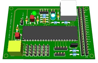
A new board is coming for the PSCockpit System: Displays & Gauges Board.
This new board drives the gauges and displays of the F16 pit reducing the load of the PSCockpit Main Board by reducing its processing time.
The Displays & Gauges Board is already configured giving a plug&play solution for people with less electronic knowledge.
PSCockpit users can use the same PSCockpit boards they already have in their pit and/or redistribute the boards between both systems PSCockpit Main Board and PSCockpit Displays & Gauges Board.
The modular concept of the Displays & Gauges Board allows users to select the displays and gauges they want to drive in their pit, adding other elements at any time.
For desktop pits or mini-pits users the Displays & Gauges Board can drive eyebrow lights, indexer lights and some other lights of the F16 Center console.
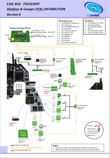
The Displays & Gauges Board is able to drive the following elements of the F16 pit:
- (2) x PSCockpit OLED displays for DED and PFL displays.
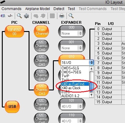
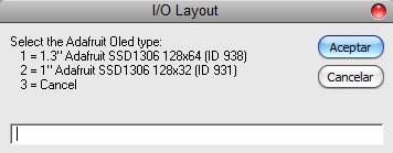
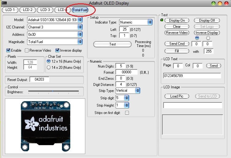
- (2) x Adafruit Monochrome OLED displays for Fuel Flow and Total Fuel indicators
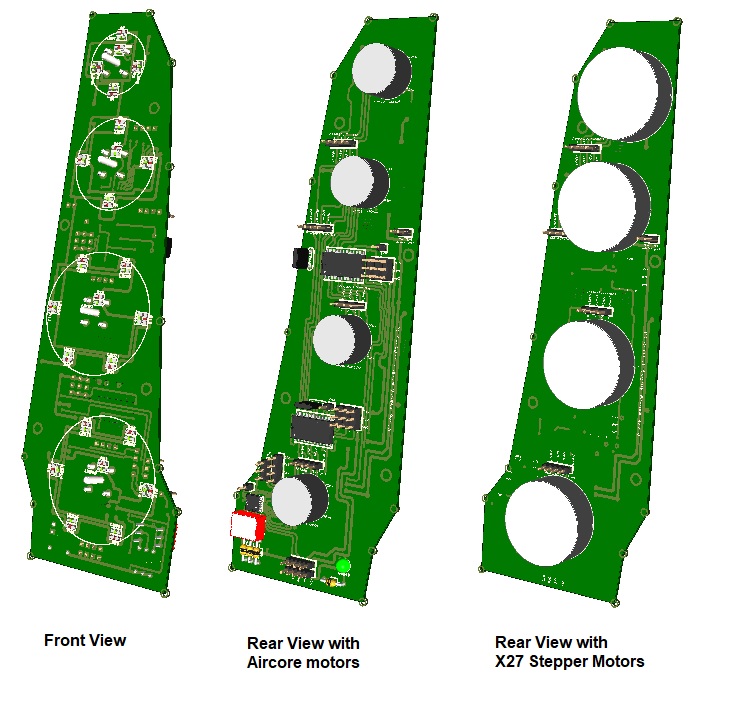
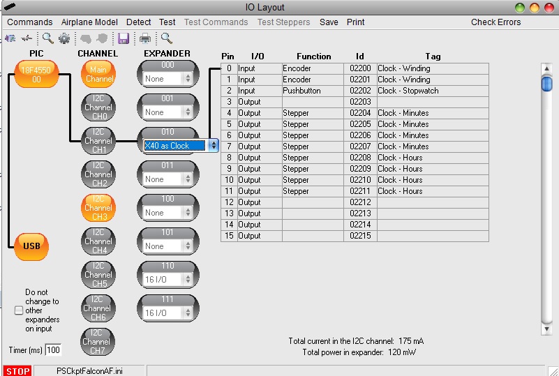
- (14) x Stepper motors X40 or X27 for LIQ OXY, EPU Fuel, HYDA, HYDB, Total Fuel, Watch, Cabin Pressure, Roll Trim, Pitch Trim, Oxy Press, Speed Brake and Compass (with Unipolar Stepper Motor) gauges
- (4) x Aircore motors for Oil Pressure, Nozzle Pos, RPM and FTIT engine gauges.
- (2) x PSCockpit 16I/O boards for Eyebrow Lights, NWS and AOA lights, LG lights
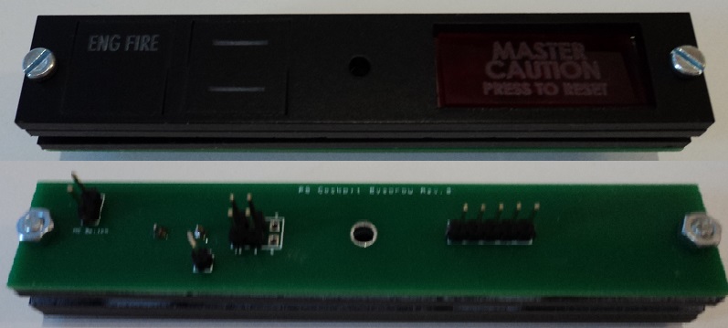
- (1) x PSCockpit Caution Panel board.
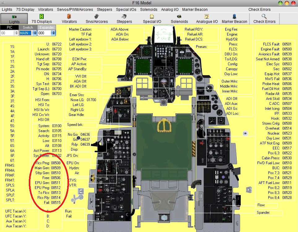
The Displays & Gauges Board distribution for the F16 is the following:
You can download the F16 Displays & Gauges Distribution here:
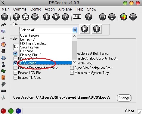
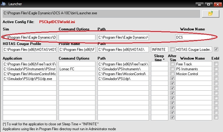
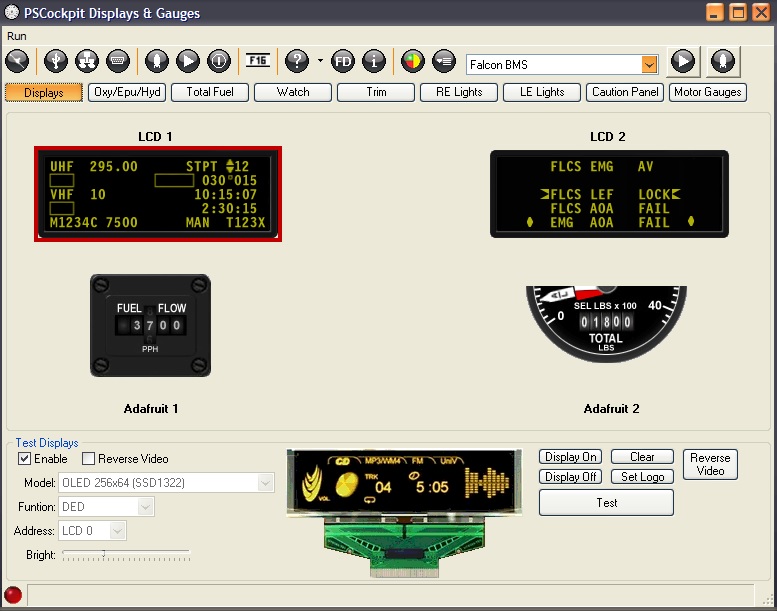
http://www.mediafire.com/file/j5p0gxo393t04q5/fileThe Displays & Gauges Board has its own standalone software for Falcon BMS and DCS sims:
For new users, the Displays & Gauges Board, depending on your needs, can be completed with the following PSCockpit items:
- DED display: (1) PSCockpit OLED display
- PFL display: (1) PSCockpit OLED display
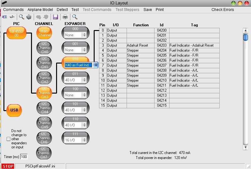
- Total Fuel Indicator: (1) PSCockpit X40 pcb + Adafruit display + X40 stepper motor
- Watch: (1) PSCockpit X40 pcb + Adafruit display + X40 stepper motor
- LIQ OXY, EPU Fuel, HYDA and HYDB gauges: (1) PSCockpit 16 I/O pcb + (4) PSCockpit X27 pcb + (4) X27 stepper motor
- Roll Trim, Pitch Trim, Oxy Press, Speed Brake gauges: (1) PSCockpit 16 I/O pcb + (4) PSCockpit X27 pcb + (4) X27 stepper motor
- Right Eyebrow and NWS lights: (1) PSCockpit 16 I/O pcb
- Left Eyebrow, AOA and LG lights: (1) PSCockpit 16 I/O pcb
- Caution Panel: (1) PSCockpit Caution Panel pcb
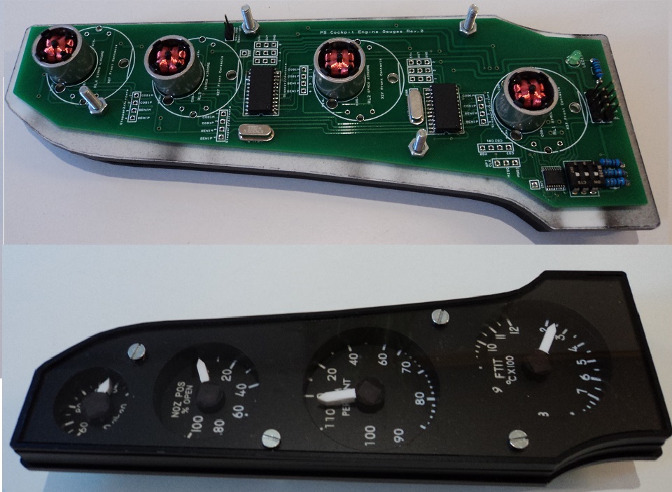
- Engine gauges: (1) PSCockpit Engine Motors pcb + (4) Aircore motors
New boards for this run are:
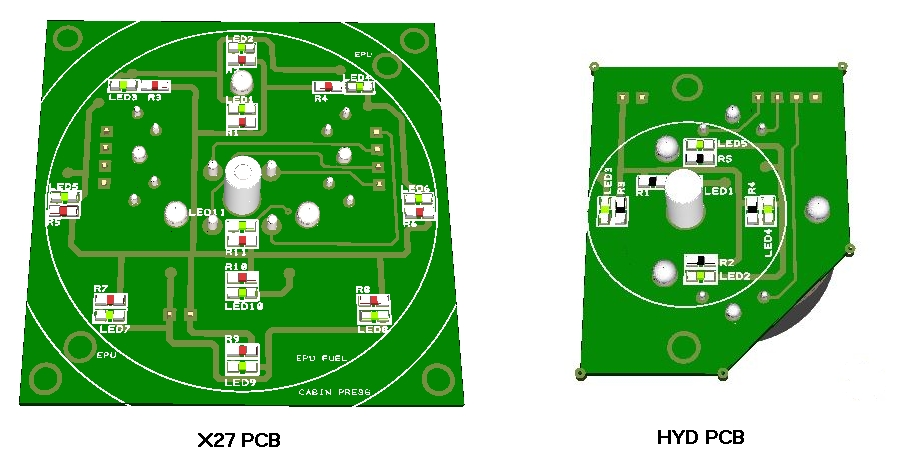
- X27 pcb
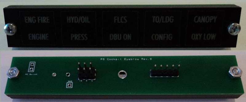
- Eyebrow lights pcb
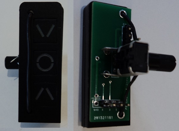
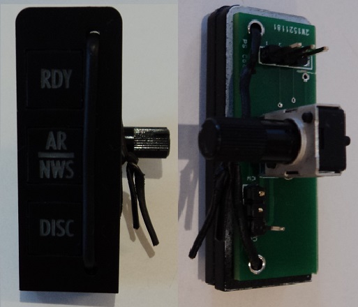
- Indexer pcb
- Engine Gauges pcb
- Hyd pcb
All the new boards come with accessible pins of all the elements and can be used outside the PSCockpit system.
The minimum quantity to manufacture the new pcbs in this run is 15 units/each.
More info about these boards will follow.
You can find more info about PSCockpit system here:
http://psfalcon.blogspot.com.es/2015/05/pscockpit-system-up-to-date-software.htmlPrices
The prices of the PCB’s already mounted and tested are the following:
- Displays & Gauges pcb: 55€
- X27 pcb: 15€
- Eyebrow lights pcb: 15€
- Indexer pcb: 15€
- Engine Gauges for Aircores with electronics for PSCcokpit System pcb: 90€
- Engine Gauges for X27 or Aircores without electronics: 65€
- Hyd pcb: 15€
Other components by demand:
- Wire and connectors
- Engine Gauges, Eyebrow and Indexer panels
- Gauges panels
- Stepper motors X27
- Aircore Motors
- Shipments: 10€/ 18€ / 28€ depending on the total weight order and country
Time Line:
- Orders will be accepted until Oct. 12th. 2020
- Payments: Until Oct. 18th. 2020. Only direct bank transfers. Sorry for the inconvenience.
- Delivery: Dec 2020
Regards,
Shep

 :
: