The TRIM board has been designed to drive (3) pots for yaw, roll and pitch trims and (2) X27 stepper motors for roll trim and pitch trim indicators. This configuration allows to have the indication of pitch trim and roll trim in both trim AP and MANUAL modes and the pots will drive the analogue trim axes in your simulator.
The pots are not motor-driven but the TRIM board has mounting holes to develop this function in the future.
The TRIM and TRIM INDICATOR boards have been designed to work in conjunction to complete the Trim panel of the F16.
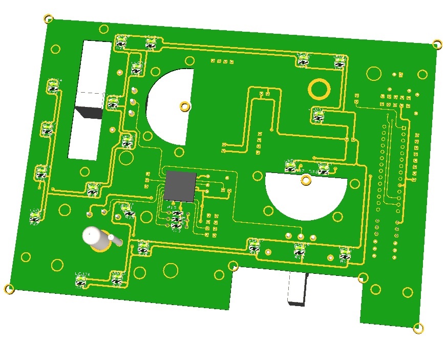
The TRIM board comes with the following elements:
- (1) 16 I/O chip to be connected to the digital I/O I2C channel of the PSCockpit system and its elements (resistors, connectors, …) to work with 5V
- (1) analogue chip to be connected to the Main Channel of the PSCockpit system and its elements (resistors, connectors, …) to work with 5V
- (3) potentiometers for yaw, roll and pitch trims
- (1) toggle switch with locking lever
- (21) SMD leds for lettering backlight.
- (7) Free digital I/Os
- (1) Free analogue input
You will find the following elements in the backside:
- (1) Connector for backlight illumination.
- (1) Connectors for digital I/O I2C channel.
- (1) Connectors for analogue Main Channel.
- (2) Mini-switch to select digital and analogue I2C channel addresses.
- (1) Connector for free digital I/Os.
- (1) Connector for free analogue input.
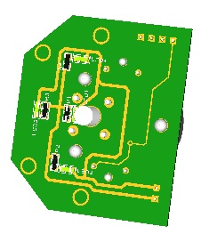
The TRIM INDICATOR board is prepared to hold an X27 589 stepper motor and is attached to the TRIM board with 4 screws leaving a gap of 5 mm where the indicator panel and indicator must be placed.
The TRIM INDICATOR board has also the necessary pins to connect the X27 stepper motor and the backlight leds to the TRIM board thus no external connections are needed to drive the stepper nor the backlight, been these driven by the TRIM board.
You will need (2) TRIM INDICATOR boards for (1) TRIM board.
The TRIM INDICATOR board comes with the following elements:
- (4) SMD leds for indicator panel backlight.
To complete the TRIM panel of the F16, you must add by yourself the following elements:
- (1) TRIM front panel
- (2) TRIM indicator panels
- (2) Indicator needles
- (1) knob for Yaw trim
- (2) circular 50 mm x 12 mm knobs for roll and pitch trim
- (2) X27 589 stepper motors
Please check the dimensions of the TRIM panels, knobs and needles at:
https://www.mediafire.com/file/qtkz1zlzesg9464/TrimPanel-A3.pdf/fileRegards,
Shep