Tuesday, November 22, 2011

PS Cockpit System - How to use steppers

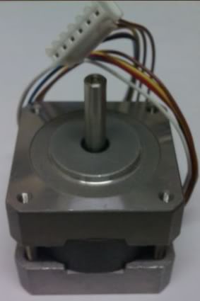
For X-27 and X40 stepper motors visit this post: link

A stepper motor is a motor which moves the rotor in a step-by-step way. This effect is achieved by sequentially turning on different stator phases in order to pull rotor to that position.


The following picture is a simplified stepper motor diagram. It can be seen that there are 4 stator poles and 2 rotor poles. Real stepper motors have much more rotor poles.


PS Cockpit System is able to drive up to 9 unipolar stepper motors with 4 stator poles using the Stp/PWM/Other Outputs card. This means that we will use 4 outputs to energize the stator poles.

The number of rotor poles defines the steps of the stepper motor. Typical steps are 3.6°, 1.8° or 0.9° and they will give us the resolution of our indicator along with the operation mode of the stepper.

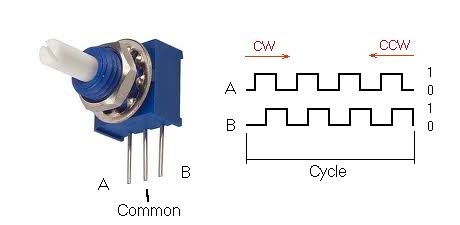
The unipolar stepper motor can be driven with to different modes:

In “Normal” mode the poles are activated in sequence A-C-D-F:


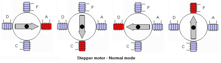
In “Half Step” mode the poles are activated in sequence A-(AC)-C-(CD)-D-(DF)-F-(FA)


As you can see the “Half Step” mode gives us the double of resolution for our indicators.

In example, one stepper motor with 1.8º steps will need 360º/1.8º = 200 steps to make a full turn in “Normal” mode and our indicator will have a 1.8º of resolution while in “Half Step” mode it will need 360º/0.9º = 400 steps to make a full turn and our indicator will have a 0.9º of resolution.

Resolution vs. synchronization

As the stepper motors are driven by energizing the stator coils or poles, we have to delay the outputs some time to let the rotor of the motor reach the position it should be in order to energize the next coil. The delay depends on the electrical characteristics of the motor, on the presence of static friction and on the external torque.

The PS Cockpit System uses timers to adjust the delay needed in each stepper motor.

So, if we set a timer of one of our stepper motor to 20ms, in “Normal” mode it will need 200 steps * 20 ms = 4 seconds to make a full turn, while in “Half Step” mode will need 400 steps * 20 ms = 8 seconds to complete a full turn.

If we are updating our cockpit with info from the sim, let’s say, every 200 ms, the indicator will always be out of synch.

Of course this is unacceptable for indicators which need speed and accuracy and so other way than the stepper motors has to be used.

Selecting the stepper motor

Ok. Too much theory for today. Let’s go for an example.

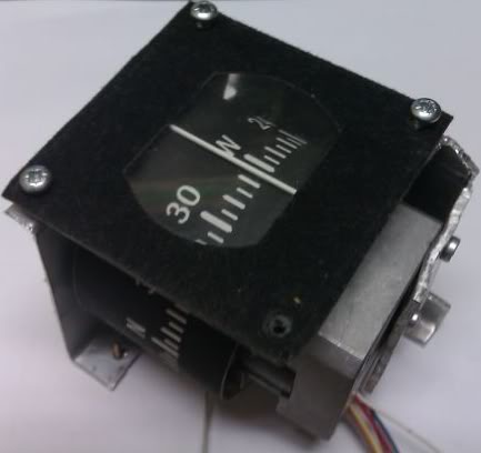
I’m thinking of driving the compass of my cockpit with a stepper motor because it needs a non-stop system as it has neither bottom nor upper limits.

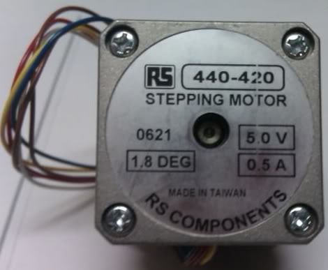
As the resolution of the compass dial is 5º, I have selected one stepper motor with 1.8º of resolution that will give me a resolution of 1.8º in “Normal” mode and 0.9º in “Half Step” mode which can be acceptable.

Also I’m going to drive a light weight indicator, so 5 VDC will give me enough torque to move it.


I’m refreshing my cockpit each 200 ms from the data extracted of my sym, so it will give me between 10 to 20 steps of rotation each time the refreshing is done using between 10 to 20 ms for each step.

That means I can drive the compass in a range of 9º (10 steps * 0.9 º/step) to 36º (20 steps * 1.8º/step) between refreshes which sounds very acceptable for this instrument.

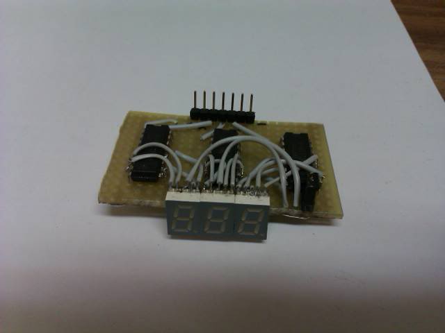
I’ve made the compass with the stepper in it:


Connecting the stepper motor

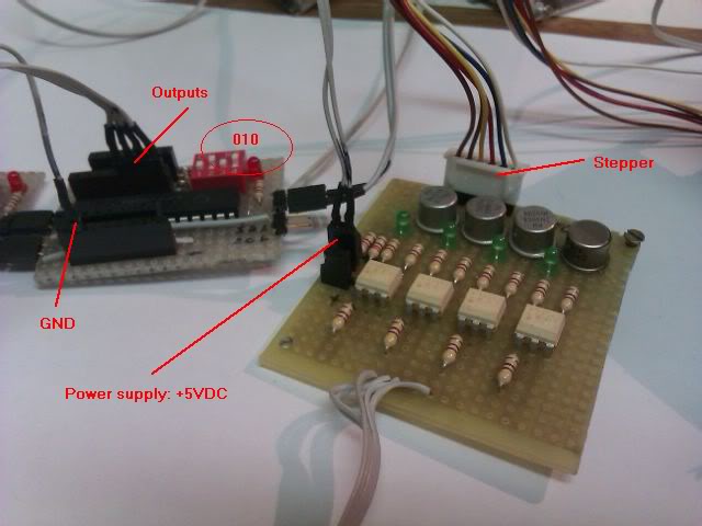
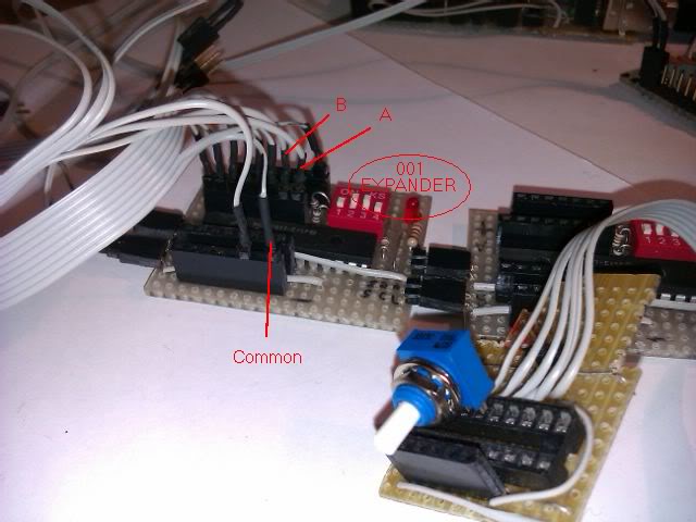
I have taken a look to the wiring diagram of the stepper motor and found the correlation coils of A-C-D-F and the common B-E of the Stp/PWM board of the PS Cockpit System:


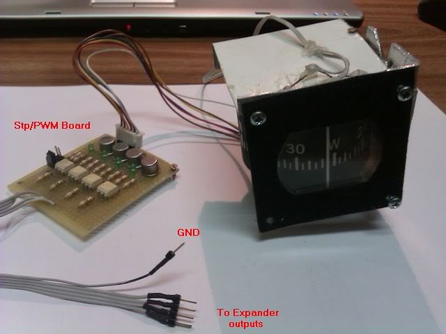
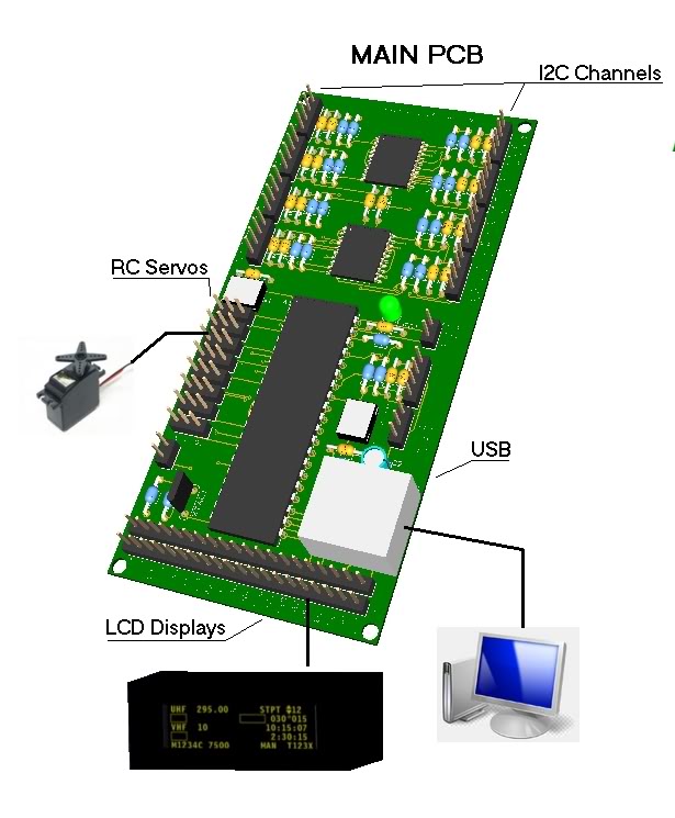
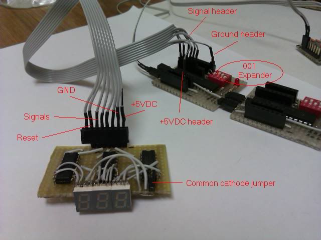
I have chosen a 16I/O expander addressed with 010 on channel 0 of the PS Cockpit System to connect the Stp/PWM board to.


Configuring the stepper motor

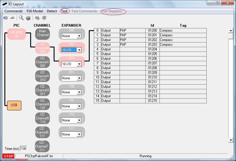
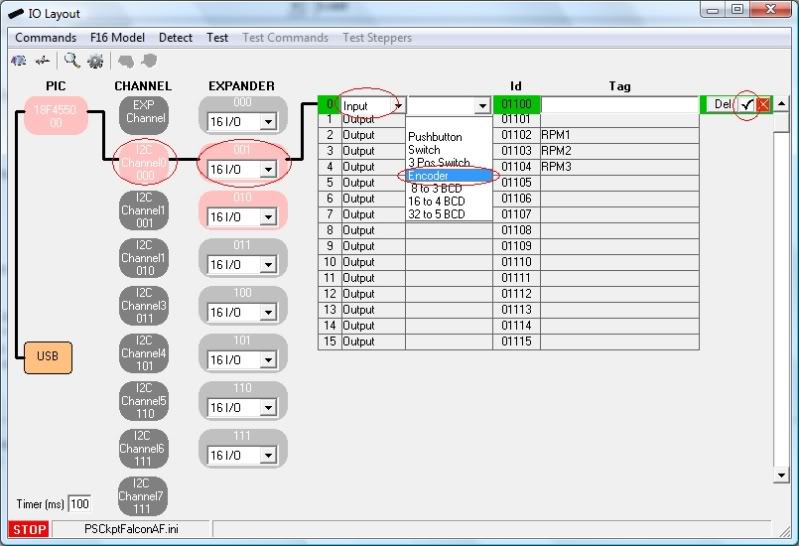
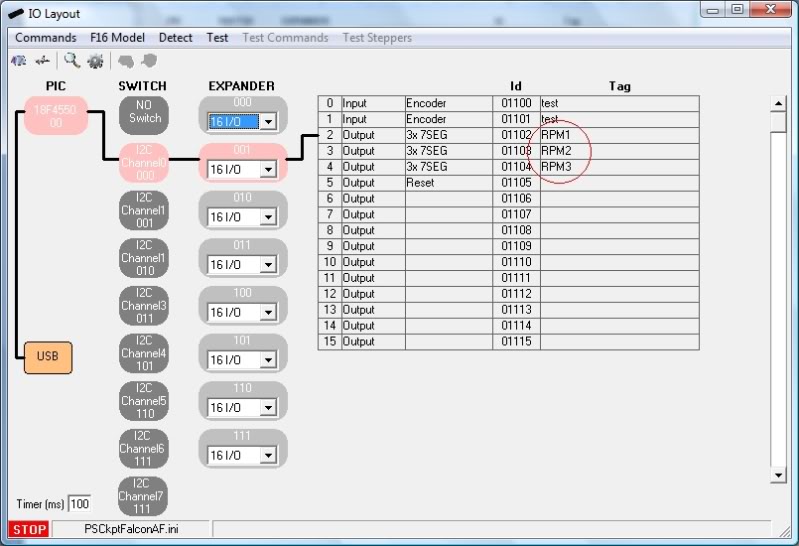
Now we have to tell the PS Cockpit Software we have connected a stepper motor to the system. For that, go to PS Layout page and select I2C channel 0 and 010 expander and select a 16I/O expander type. The list of I/O will appear on the right of the page.


On the I/O dropdown list select “Output” and on the Function dropdown list select “Stepper”. Give a tag name for the stepper -I’ve obviously named “Compass”- and accept it. The software will fill the needed outputs automatically

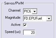
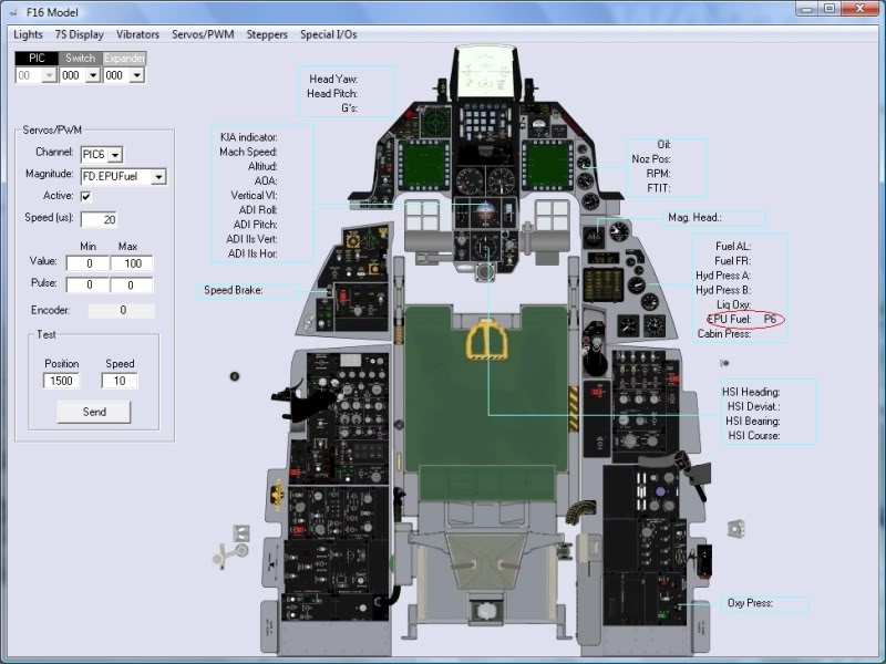
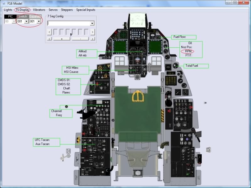
The PS Cockpit software knows now it has a stepper motor in that location but doesn’t know what magnitude it has to show on it. To do this go to the F16 model page and select Steppers:


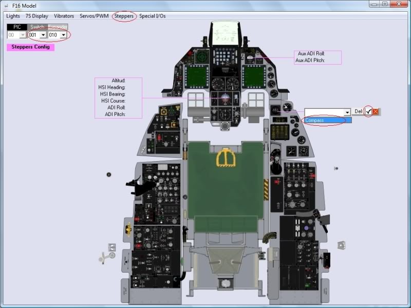
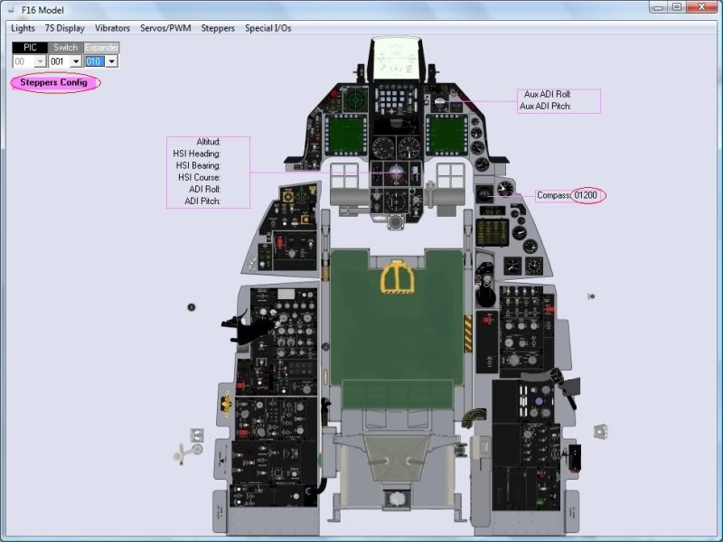
Select the I2C channel 001 and expander 001, click on the “Compass” label to see the dropdown list of all the steppers connected to that expander and select the tag of the desire stepper on the dropdown list. “Compass” in this case. Accept it and the number of the first output of the Layout page will be shown:


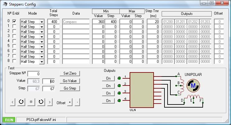
One “step” more and we are done: We have to configure the type of stepper and the values of the indicator. To do this click on “Stepper Config” label and the following page will appear:


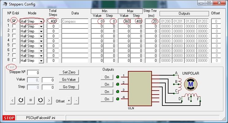
The “Stepper Config” page shows all the data of the steppers and it will be used later to test the stepper. By now we have to see that the “Compass” tag and the related outputs are showed.

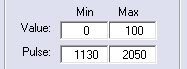
We can also put some values although we can change them when in test mode:
- Enbl: Click on the checkbox to enable the stepper.
- Mode: Select the desire mode to drive the stepper (Normal or Half Step)
- Total steps: Set the total steps of your stepper (i.e. 400 for 1.8º stepper in Half Step mode; 200 for 1.8º stepper in Normal mode; 100 for 3.6º stepper in Normal mode; 200 for 3.6º stepper in Half Step mode; …)
- Min. Value and Step: The relationship between the lower value of the magnitude and the step number. In this case 0º of the compass will be at step number 0.
- Max. Value and Step: The relationship between the upper value of the magnitude and the step number. In this case 360º of the compass will be at step number 400. This will give us a non-stop indicator.
- Step Tmr: The value of the timer in ms to wait the rotor of the stepper reach the correct position once a pole has been activated.

The test frame only will be available when in test mode.

Normally we set the maximum value of the magnitude and the maximum steps together. To change the rotation direction of the stepper set the maximum value of the magnitude at the minimum step.

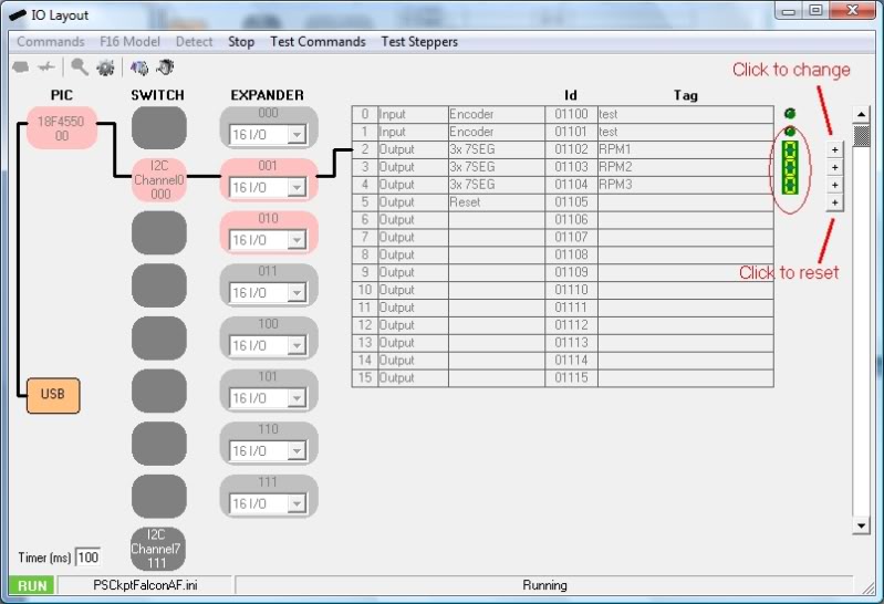
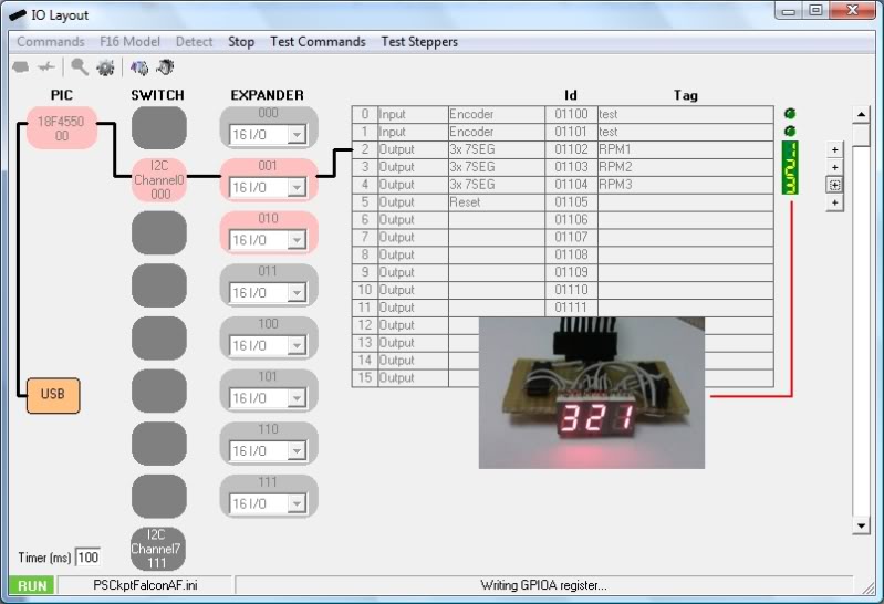
Testing the stepper motor

Close the “Steppers Config” page and the “F16 Model” page and go back to the “I/O Layout” page. Click on “Test” command and on “Test Steppers” command:


The “Steppers Config” will be shown again and the “Test” frame will be now available:


For testing the stepper you have the following tools:
- Stepper nº: Select the desire stepper to test.
- Outputs: You can activate each output individually to test them.

- Step -: Move the stepper one step backward
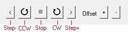
- CCW: Move the stepper continuously counter clock wise
- Stop: Stops the stepper
- CW: Moves the stepper continuously clock wise
- Step+: Moves the stepper one step forward
- Offset: In case you are using “Half step mode” you can use this tool to select and intermediate value between steps.

With the above tools you have to move the indicator to the 0 value, in this case “North” and then click on the “Set Zero” command to let the software know how many steps will need to move in relationship with the magnitude.

Once the 0 is established, you can also use the following tools:
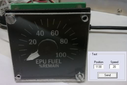
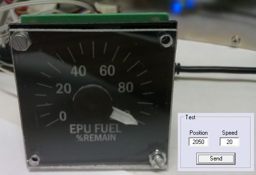
- Value: Set the value of the magnitude you want the stepper to go to and click on the “Go Value” command and the stepper will find the shorter direction to reach that value.
- Step: Set the value of the step you want the stepper to go to and click on the “Go Step” command and the stepper will find the shorter direction to reach that value.

You can also change the configuration of the steppers in the list.

The software will remember the position of the stepper even you if you exit from the application.

This video shows you how to test it. Sorry for the quality.


Regards,
Shep


Wednesday, November 16, 2011

PS Cockpit System - How to use LCD Display

PS Cockpit System PCB is able to drive up to 2 LCD graphic display modules based on the KS0108 driver. You can connect the modules to the Main PCB of the system:

The connectors pin diagram is the following:


Look closely to your LCD datasheet to find the corresponding pin-out.

I have used a Displaytech 64128C LCD graphic module with the following pin-out:


This LCD Display is a little tricky as it needs a negative supply voltage for the LCD on Vo. I turned around by using a PC power supply which gives us a source of -5VDC.

Once the LCD module has been connected the PS Cockpit System at start up will display the PS logo and when you run the PS Cockpit software the DED info will appear on the LCD.

If you only have one LCD module the PS Cockpit System can also display the PFL info in it. To do this, you have to go to the F16 model and select Special I/Os page. In the “Show DED/PFL” select the desire input from the expander (i.e. F-ACK pushbutton on the left eyebrow). Now whenever you push the pushbutton the display will show you the first screen of the PFL. Keep pushing this pushbutton to go through all the pages of the PFL. Once all the pages of the PFL have been showed the display will show the DED screen again.


Here is a video of how the Displaytech display is working as the F-16 DED with the Falcon AF sim:

Regards,
Shep

Sunday, November 13, 2011

PS Cockpit System - How to use servos

The Main PCB of the PS Cockpit System has 8 PWM output ports to drive 8 RC servo motors directly and it  (no longer supported) has build-in support to use the Lynxmotion SSC-32 board for an added 32 servos more. This board is connected to a serial port of your PC. Please read the SSC-32 manual for connecting and supplying power to the servos.


To use the servos of the PS Cockpit System Main PCB you need first to supply power to the servo power supply header. Usually the servos are powered with 6VDC but you can use 5VDC from the power supply of your cockpit (i.e. PC power supply).

Be very careful to connect the servo and the power supply to the right pins, otherwise you will ruin the servo.

As the power is supplied to all servos they have to be of the same voltage.

Be aware of the type of your servo: Most of the servos can move up to 180º of rotation but they can be damaged when commanded past their mechanical limitations. PS Cockpit system limits the movement of the servo up to 170º for conservative purposes. Some servos have only a 90º of motion. I don’t recommend using these types of servos as the precision of the gauge we are trying to drive will be lower.

As the range of the servo will be limited to 170º you will need a gear system to drive gauges that past this 170º movement. For better resolution choose a gear system with many teeth as possible and with a relation that better fits the 170º to the range of the gauge.

For this example I have chosen the EPU Fuel gauge with a Cyclone CY130011 which gives us a torque of 0.8 Kg/cm at 4.8VDC. As the EPU Fuel gauge has a total movement of approximately 240º I have chosen a gear system of 32/10 so I will need 90º of rotation of the servo for 288º of the gauge (90 *32/10=288º).

I have connected it to the port 6 of the servo header.

The configuration of the servo is done in the F-16 Model page selecting “Servos/PWM”. In the left frame you have to set the following parameters:


- Channel: The output you have connected the servo. The syntax used is a number for the Lynxmotion SSC-32 channel and “PIC” + number of the servo channel for the PS Cockpit Main PCB. So I select “PIC6” for my example.
- Magnitude: The magnitude of the sim which is going to be tied to the servo. “FD.EPUFuel” for my example.
- Active: Select the checkbox if you want the servo to be active.
- Speed: The speed you want the servo to be moved from one position to another. A lower value means a more smoothness movement of the servo but also a less synchronization of the reading with the sim. The speed parameter is very useful to reduce the noise of the servo and for avoiding heavy strokes on it so you should find a value of each gauge to accomplish smoothness with accuracy.

Once the data has been set you will see the F-16 model screen updated:


Now we are going to set the servo movement range and make the relationship with the magnitude. The RC servos in the PS Cockpit System have a resolution of 1500 units from 750 to 2250. These figures represent the wave length in ms multiplied by 1000 which are going to be sent to the servo each 20 ms. (1500 = 1.5 ms).

The 750-2250 range limits the movement of the servo up to 170º for conservative purposes. For servos with only a 90º of motion you have to adjust the pulse from 900 to 2100.

Using the Test frame and taking in account the above considerations we have to move the servo to the 0 and the 100 positions of the gauge scale and save the values:


Now we have the values of the position of the servo we can set the parameters of the magnitude:


This servo is driven clockwise, for counter clockwise operation mode, just change the value between them, having 100 in the Min value and 0 in the Max value. The software will do the rest for you.

For gauges that have no linear scales like FTIT, RPM and ASI the software will calculate the new ranges for the servo to move correctly. Wink

For gauges that have no linear scales like FTIT, RPM and ASI, see Step 7: Adding intermediate scales to your gauge in the following post: HOW to Use Aircores

Best regards,
Shep

Saturday, November 12, 2011

PS Cockpit System - How to use encoders


A rotary encoder is an electro-mechanical device that converts the angular position of a shaft to a digital code. The type of encoders PS Cockpit System uses are the incremental encoders which provides information about the motion of the shaft by enabling cyclical outputs when the encoder is rotated.

The incremental rotary encoders have typically one common and two outputs which are activated as the shaft is moved:


The total count of pulses per revolution gives as the encoder cycle.

The signals A and B are decoded by the software this way:
- Clockwise turn if a sequence of A(1)B(0), A(1)B(1), A(0)B(1) is detected.
- Counter clockwise turn if a sequence of A(0)B(1), A(1)B(1), A(1)B(0) is detected.

If the encoder is turning too fast, an invalid transition may occur, such as A(1)B(0) ->A(0)B(1) and there is no way to know which way the encoder turned. If the encoder is turning even faster, a backward count may occur.

To avoid invalid transitions I strongly recommend using encoders with a maximum of 16 pulses per revolution.

To improve the performance of the encoders you can use the following setup: link 

You will get the best performance of the encoders and PSCockpit boards when configuring the Main Board in “Expander Interrupt” mode. See this post:  link

How to connect encoders to expanders

Just connect A y B pins to the inputs of the I/O expander and the common to ground. I have chosen in our example the expander 001, pins 0 and 1.


Let’s go to configure the encoder in the software:
- Select IO Layout page.
- Select I2C Channel 001
- Select expander 001
- Select Input
- Select Encoder
- Set the tag you desire
- Accept


I have named this encoder as “Interior Light”.

Now I will set the commands. I have selected the following callbacks in Falcon BMS:
- SimInteriorLightCW (turns the INT LIGHT knob clockwise) : Shift +A
- SimInteriorLightCCW (turns the INT LIGHT knob counterclockwise): Ctrl + A

Go to the PS Commands page and select “Encoders”. A list of all the encoders configured in the IO Layout page will appear. Select the “Interior Light” CW Turn field and press the key combination, in this case, “Shift + A”. Accept it by clicking on “Replace” and repeat the process for the CCW command.


Time to test it. In the I/O Layout page click on “Test” and you’ll see how the inputs of the encoder activate the simulated leds on the right as you turn the encoder clockwise or counter clockwise:


If you click on “Test Commands” a frame will appear where the key combination we have chosen are sent:


Assigning an encoder to a dimmer function

In a previous “how to” we have already seen how to set a dimmer function with a PWM signal coming out from the servos pins of the PS Cockpit System Main PCB.

To assign an encoder to the PWM signal we have to go to the F16 Model page and select Servos/PWM. In this page we have to select the desired servo/PWM in the Channel dropdown list and select “Dimmer” in the Magnitude dropdown list.

Now we can enter the encoder is going to drive the PWM signal clicking on the field “Encoder” and selecting the corresponding one in the dropdown list:


Don’t forget to click on the Active checkbox.

Now the encoder is tied to that PWM signal. We can also tell the software the amount of change we want by entering in the “Speed” field a quantity from 1 to 255. This is the quantity the software is going to add/subtract to the PWM signal. Less quantity means more encoder turns to get the full bright of the dimmer.

If the PWM signal goes down to a certain quantity then the dimmer will go OFF.

The data of the dimmers is stored by the software so at start up the dimmer will go to the same position it was when we exited the software. There is no need to adjust the encoder every time we enter the cockpit.

As the encoder will drive the PWM signal and will send the commands to the sim you will be dimming your cockpit and, at the same time, the lights of the sim. Just adjust your dimming speed to get in synchrony with the sim. Laughing Out Loud

To test it we have to go back to the I/O Layout page, click on “Test” and activate “Test Commands”. The following video shows it working, sorry for the low quality.


Regards,
Shep

Sunday, November 6, 2011

PS Cockpit System - How to 7 segment displays

HOW TO use 7 segment displays with the PS Cockpit System Clapping hands

PS Cockpit System PCB for 7 segment displays is able to drive up to (6) Avago 7 segment displays. The Avago 7 segment displays are not supplied with the PCB so you can use the ones you like (Kingbright, Lite-On, …) . Just carefully connect the pins of the segments to the PCB. The 7 segments displays have to be common cathode and 5VDC if you want them to be sourced by the PS Cockpit System.


The 7 segment displays PCB has three different headers:
- Expander header: used to connect the PCB with the desired expander. It has the 5VDC supply, ground, one signal for each display and the reset pin for all the displays.
- Common cathode header: used to be connected to a dimmer system. If no dimmer solution is going to be used then a jumper must be plugged in.
- Dot header: if you have a number with a decimal dot, you can select where do you want the dot to be positioned placing a jumper between the first pin and pin of the desired display.


The board has a total length of 70 mm and a total height of 47 mm and it is designed to plug directly Avago 7.6 mm models A803 (yellow) or A903 (green) and has the connectors and the chips on the back side to mount the PBC directly onto the panel.

If there is any device blocking this type of mounting you can use the Andon socket for the Avago displays so the PCB will mounted tangent to the panel:


Is it too expensive for you? Or, do you want to use other smaller or different brand displays? Then you can always glue the displays on the border of the PCB and wiring the pins to the PCB Whistle:


There is no need to use the 6 displays on the board, you can choose by software 3, 4, 5 and 6 displays.

Ok. Now I have 3 displays I’m going to use as the rpm indicator of the falcon sim. Let’s first connect the PCB to the desired expander, of course the nearest one I have in my cockpit. This is going to be the 001 expander of the I2C Channel 0:


Carefully connect the following wires:
- +5VDC to the +5VDC header of the expander
- GND to the GND header of the expander
- Signals and reset to the signals header of the expander. Depending on how many displays you want to drive you have to connect 4, 5, 6 or 7 wires. Remember, one wire for each display plus one for the reset. I have selected pins number 3, 4 5 and 6 of the 16 IO expander.

Let’s configure the software: Select IO Layout, I2C Channel 0 and expander 001 so we have the list of IOs of that expander. Select “Output” on the first dropdown list and “3x7SEG” on the second dropdown list.


The software automatically will fill the following lines according to its needs when you accept and you can fill the tag field as desired:


Time for testing: Click on the Test command, you will see a 7 segment display icon with the number you have on the display. Click on the “+” command on the right and the number of that display will change accordingly. Click on the “+” command of the reset pin and all the displays will go to 0:


Everything is going fine Yihaw !.
Just one final step and we are done: we have to tell the software that we want this display to be the rpm of the sim. To do this, go to the F16 Model screen and select 7Seg Display where you will see all the data of the F16 that can be showed in this type of displays:


Now select the switch and the expander and click on RPM a dropdown list will appear with the 7 Segment Displays configured on that expander, in this case, the only one we have configured called RPM1. The first pin of this display will appear near the tag RPM.

Now we have to configure the format of the number. In the “7 Seg Config” panel select RPM on the dropdown list and will appear the number of digits you have in your display, 3 in this case.


Now we can format the number with the following tools:
- Moving the 3 numbers to the right or to the left.
- Adding/removing digits.
- Moving the decimal point to the right or to the left.

I’m going to use the RMP with one decimal so I adjust the format accordingly:


Now I run the PS Cockpit software in normal mode and run our favourite sim. I have used FalconAF for this example:


Sorry I don’t have the decimal point option in this PCB DOH !.

Edited on Apri 11th, 2016
--------------------------------------------------------------------------------------------------------------------------
You can also use one 6 digits 7 segment display pcb to show to different magnitudes. To do this, follow this procedure:
1. Select the same address of the 7 segment display in the Airplane model:


2. Select the first magnitude in the dropdown list and configure the digits in such way that the magnitude will use the 123 digits:


3. Select the second magnitude in the dropdown list and configure the digits in such way that the magnitude will use the 456 digits:


--------------------------------------------------------------------------------------------------------------------------

Regards,
Shep