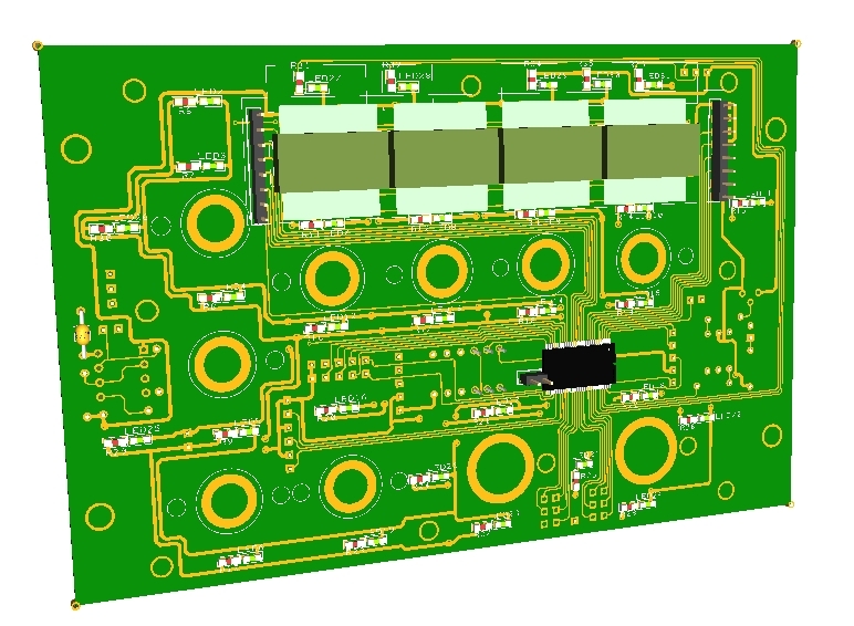
For UHF Board description, options and how to configure the expander address, see PSCockpit Quick Guide V.4 – UHF PCB. You can access the Quick Guide from Help/Quick Guide menu in the PSCockpit software.
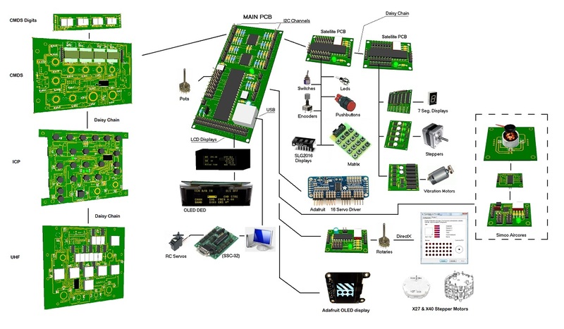
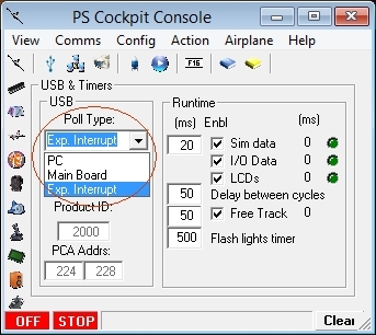
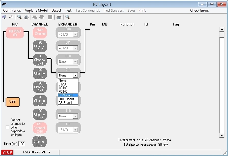
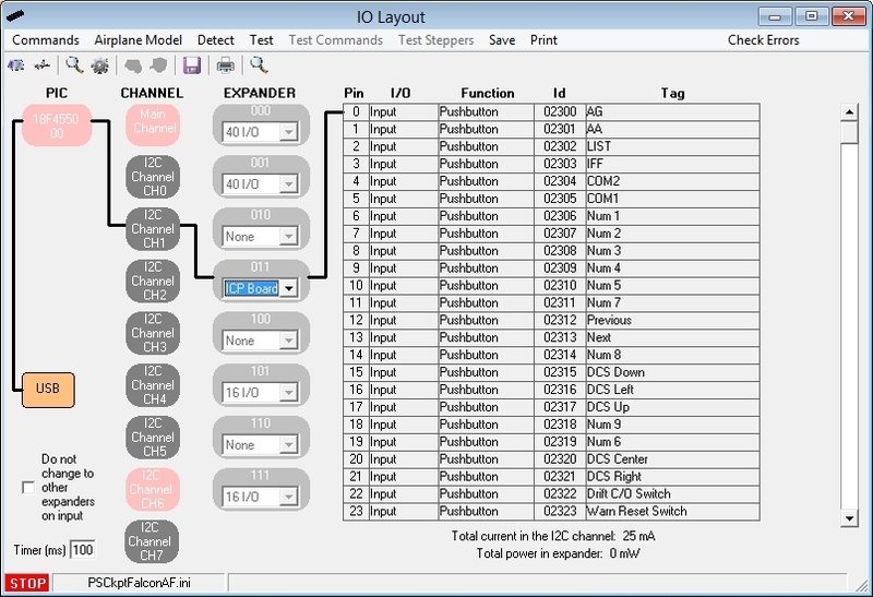
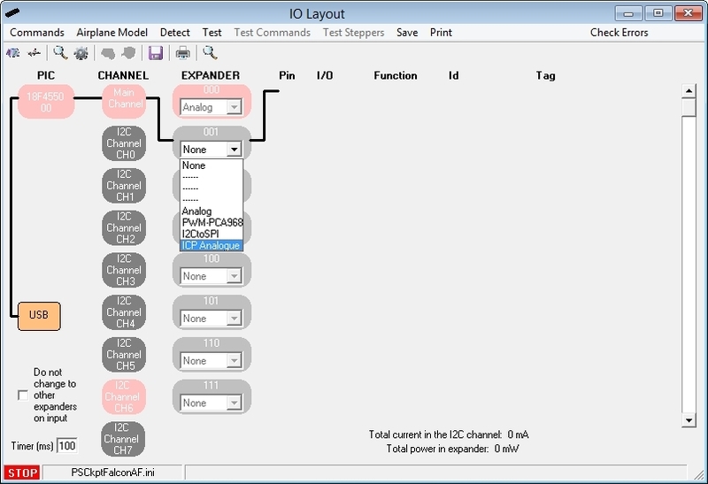
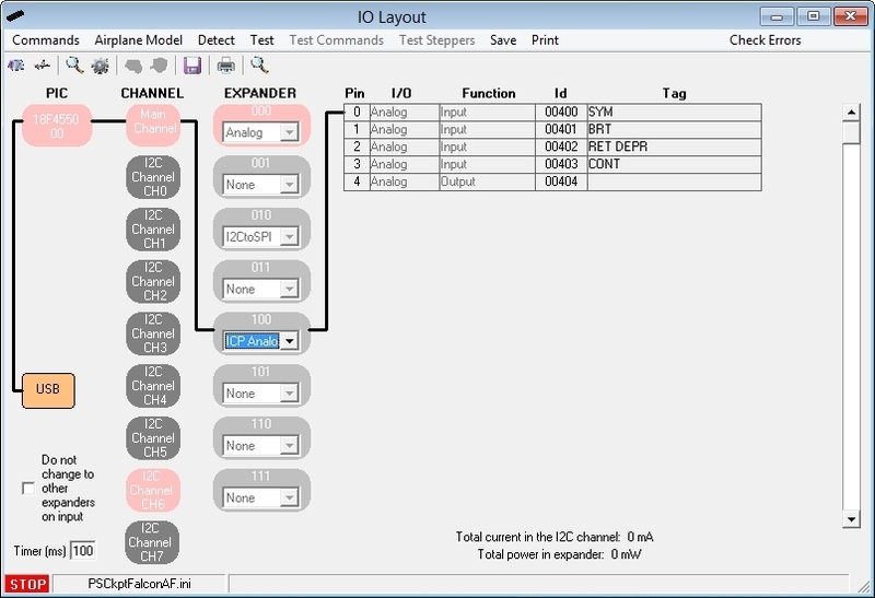
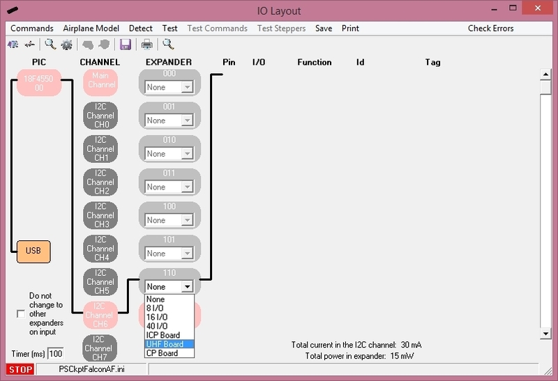
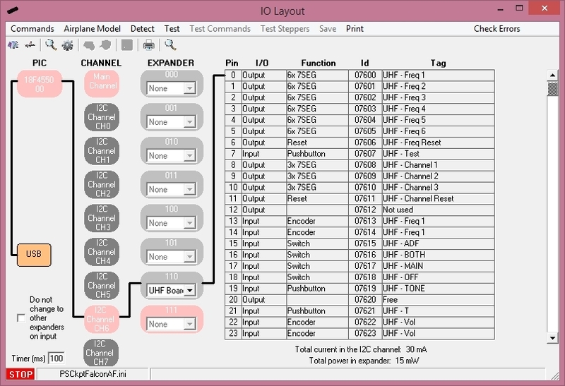
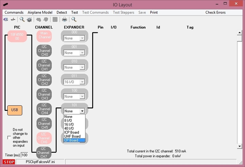
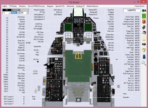
To configure the PS Cockpit UHF panel just select UHF Board from the Expander pull down list in the IOLayout page of the PS Cockpit Software at the correct I2C channel and expander configured in your UHF board:
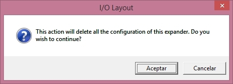
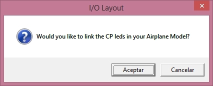
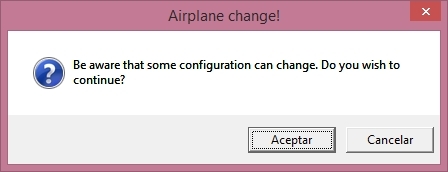
In case of there is some data already in the selected expander, the software will prompt you for continue:
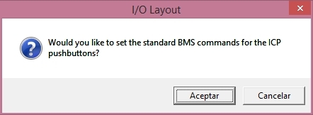
If you have the F16 Model Airplane, you will be prompted to:
- Set the standard BMS commands for the UHF board.
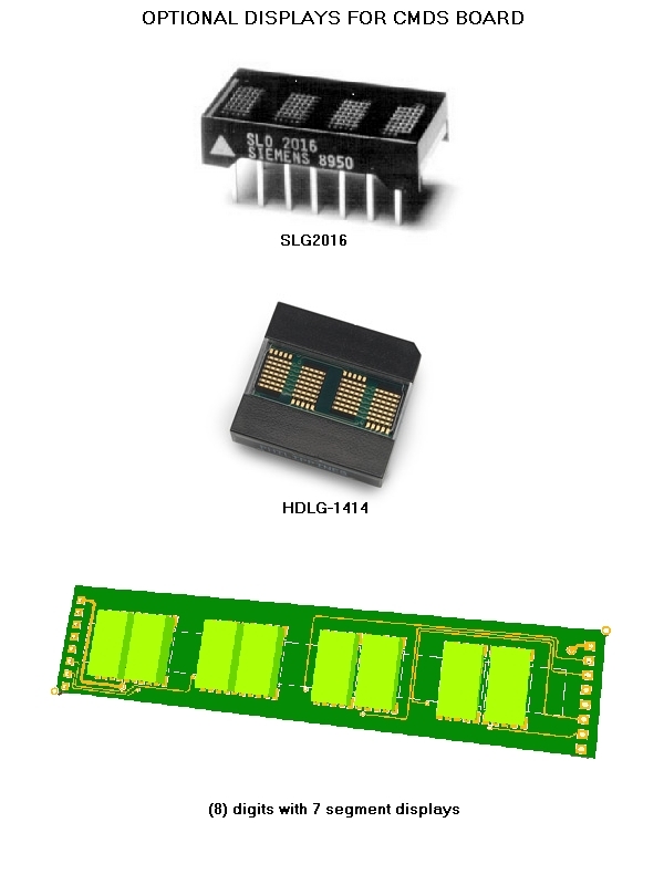
- Link the 7 segment displays to your Airplane model.
- Use internal values for UHF frequency and channel.
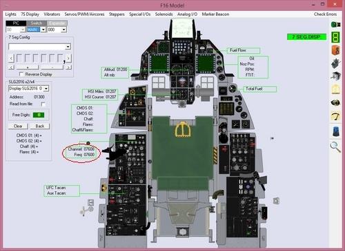
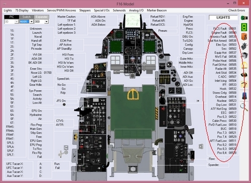
If you answer affirmative to the prompts, the UHF board will be ready to use and the F16 Model and Commands pages will show up with all the data already in the correct location:
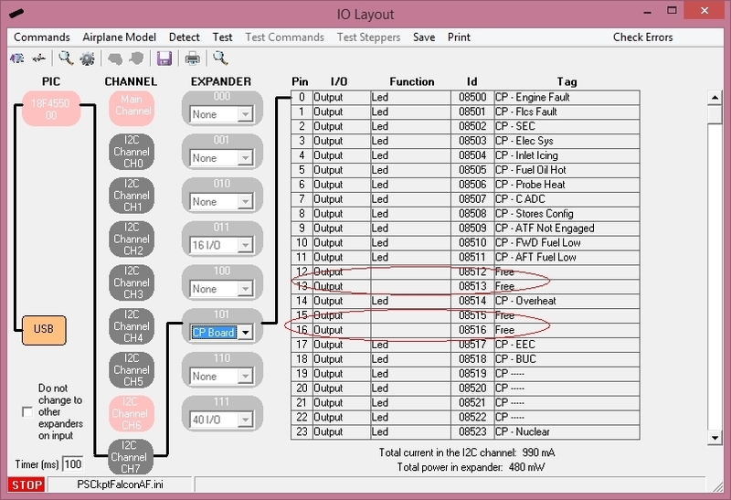
Once the UHF panel is already configured you can modify the list of inputs/outputs as desire as well as the free I/O of the expander:
Be aware that once the configuration is saved, whenever you enter the IOLayout Page
you won’t see “UHF Board” label on the expander anymore but the 40 I/O label.
UHF Frequency and Channel internal values
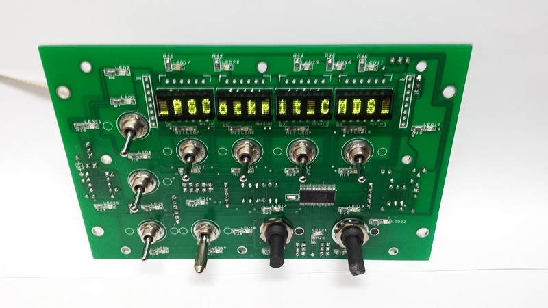
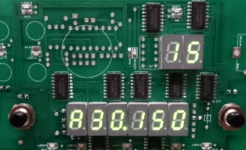
As BMS do not provide yet the values of the UHF Frequency and UHF Channel in the share memory area, you can choose to use the PS Cockpit Software internal values. This way, you will see the internal values of them displayed fancy in your UHF panel:
This values will be modified with the encoders of the UHF panel accordingly.
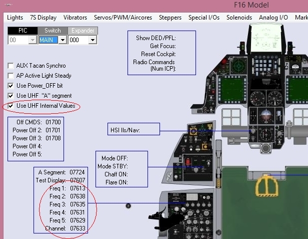
To use this function open the F16 Model page, go to Special I/Os and select “Use UHF Internal Values” and fill the ID of the encoders in its location:
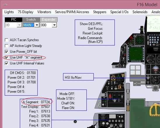
UHF “A” segment display
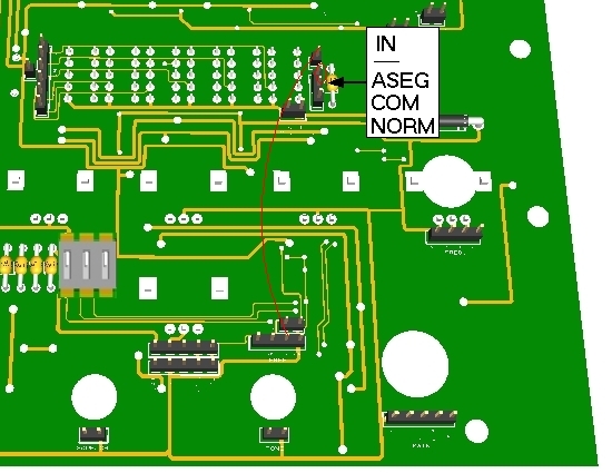
By default you UHF board is shipped with the first display of the UHF frequency in normal mode. This means that you will see standard numbers in the display. If you would like to see only “2”, “3” and “A” instead, you have to change the configuration of your board as follows:
1. Move the jumper to its original position COM-NORM to ASEG-COM.
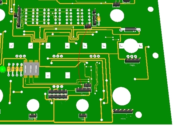
2. Wire one free output from the board (by default output 24) with the IN pin of the connector.
3. In the PS Cockpit Software, select “Use UHF “A” Segment” in the Special I/Os page of the F16 Model and add the output ID in its location:
Power OFF bit
When the board is power ON, the 7 segments displays will display a value of (0). As with the 7 segment display boards, the displays can remain OFF until you energize the pit inside the simulator -as in the real life- using the Power OFF bit.
To use this function, follow the next procedure:
1. Detach the jumper from the Power OFF bit connector of the UHF board.
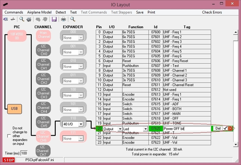
2. Wire a free output from the board to the left pin of the Power OFF connector (i.e. free output 20):
3. Select a Led Output for the output 20 in the IOLayout.
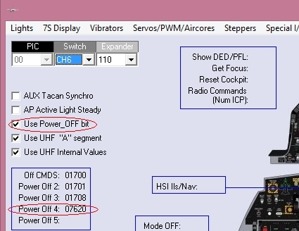
4. Select “Use Power OFF bit” in the Special I/Os page of the F16 Model and add the output ID in one of the Power Off reserved locations:
Just remember the next time you power ON your cockpit that the board is not faulty but you are using the Power OFF bit!!
Regards,
Shep