
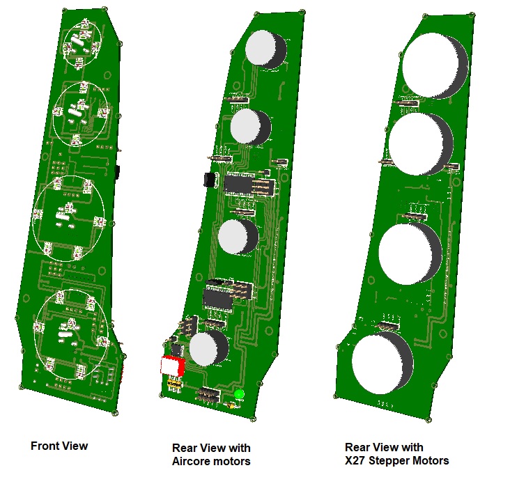
The Engine Gauges pcb has been designed to hold and drive (4) Aircore motors to simulate the F16 engine gauges -OIL, NOZ POS, RPM and FTIT- and backlight the gauge dials.
Alternatively, the board can be used to hold (4) X27 stepper motors. In this case, the board will be supplied without electronics. Be aware that the X27 stepper motors response driven with the PSCockpit System is quite less sensitive than the Aircore motors. The X27 stepper motors are recommended for low speed gauges as EPU Fuel and others.
The board comes with the following elements:
- (1) I2CtoSPI chip to be connected to the Main Channel of the PSCockpit Main Board or to one of the connectors of the PSCockpit Displays&Gauges Board and its elements (resistors, connectors, …) to work with 5V
- (2) driver chips for Aircore motors
- (25) SMD leds for gagues backlight.
You will find the following elements in the backside:
- (1) Connector for backlight illumination.
- (2) Connectors for I2C channel.
- (1) Mini-switch to select I2C channel address
To complete Engine Gauges pcb you must add by yourself the front panel, gauge dials, pointers and Aircore motors.
The Engine Gauges pcb can be used with the HISPAPANEL “F-16 Engine gauges
Model MC11” panel.
You can check the dimensions of the Engine Gauges pcb at:
http://www.mediafire.com/file/wz5cbmbtq1cja16/EngineGaugesPCB-A3.pdf/file
Regards,
Shep
do you have a type or spec for the aircore motors needed? I am having a hard time finding them
ReplyDelete