I’ve been working on the X27 168 stepper controllers to find that there is no need to make a board for these steppers.
They can be connected directly to an I/O board with the following two limitations:
- It won’t be valid for high speed gauges (i.e Altimeter). This is because the motor has a 1:180 gear ratio and needs 6 steps for one motor turn. That gives us 1080 steps for a 360º dial.
- It will only valid for gauges with equally distributed scale.
Good thing is that we can use them for Cabin Press, EPU Fuel and Hyd Press gauges and even Clock and Fuel Gauge using the X40.879 which comes with a double coaxial independent shafts.
Regards,
Shep

Saturday, November 22, 2014
UHF Pcb for the PSCockpit System
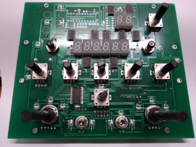
The new UHF board has been designed with (1) 40 I/O chip that can be connected to the digital I/O I2C channel of the PSCockpit system. It comes with corresponding elements (resistors, connectors …) to work with 5V and one selectable mini-switch to select the desire I2C address.
Also included are the following components:
- (2) Mini pushbuttons.
- (2) Rotary switches
- (7) Incremental encoders for digit selection, channel selection and volume.
- (9) 7 segment displays for frequency (6) and channel (3)
- (2) Mini toggle switches 3 positions
- SMD leds for lettering backlight.
You will find the following elements in the backside:
- (1) Connector for backlight illumination.
- (2) Connector for digital I/O I2C channel,
- (1) Miniswitch to select digital I2C channel address
- (1) Connector for free digital I/O of the 40 I/O board. You can use them to connect other switches.
To complete the UHF you will have to add by yourself the front UHF panel.
You can check the following dimensions of the UHF panel at
http://www.mediafire.com/view/u1924z4u3fj65el/UHFPanelFinal.PDF
Regards,
Shep
Thursday, November 6, 2014
PSCockpit A10C distribution file
For A10C supporters,
You can download the A10C Cockpit distribution file at:
http://www.mediafire.com/download/9c1olf99c9z7c8b/PSCockpitDist_A10C.rar
Regards,
Shep
You can download the A10C Cockpit distribution file at:
http://www.mediafire.com/download/9c1olf99c9z7c8b/PSCockpitDist_A10C.rar
Regards,
Shep
Tuesday, November 4, 2014
PSCockpit Caution Panel PCB and Caution Panel Extension PCB
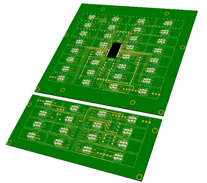
The PSCockpit Caution Panel PCB is ready to be connected to the PSCockpit system as an extension board in any of the I2C channels. It comes with its own 40 I/O chip and the selectable I2C address switch.
The Caution Panel Extension has been designed to extend the Caution Panel to be used in the A10 cockpit. It is connected to the Caution Panel and no more cables are required. It comes with its own 16 I/O chip and the selectable I2C address switch.
Just remember that you can only connect 8 extension boards per I2C channel.
Main Features:
- SMD leds in two colours -green and yellow- selectable by a rear switch.
- 8 free I/O in the Caution Panel.
- All connections in the back side.
Dimensions:
- Caution Panel pcb: 115,5 x 104 mm
- Caution Panel Extension pcb: 115,5 x 47 mm
Regards,
Shep
Sunday, November 2, 2014
PSCockpit System Fourth Run!!!
New run to adquire boards of the PSCockpit System.
Follow this link: http://www.viperpits.org/smf/index.php?topic=9774.msg133644#msg133644
Regards,
Shep
Follow this link: http://www.viperpits.org/smf/index.php?topic=9774.msg133644#msg133644
Regards,
Shep
Wednesday, May 21, 2014
Monday, May 12, 2014
HOW to Use AIRCORES in PSCockpit System
Implementing Aircores in PSCockpit System is not an easy task (at least at the beginning) as you have to deal with three different boards and some other configuration options. This guide will help you to find your way easily to reach your goal.
Basically, the system consists of 3 different boards:
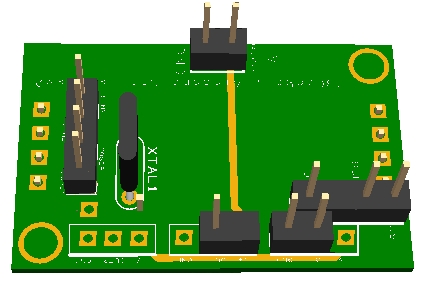
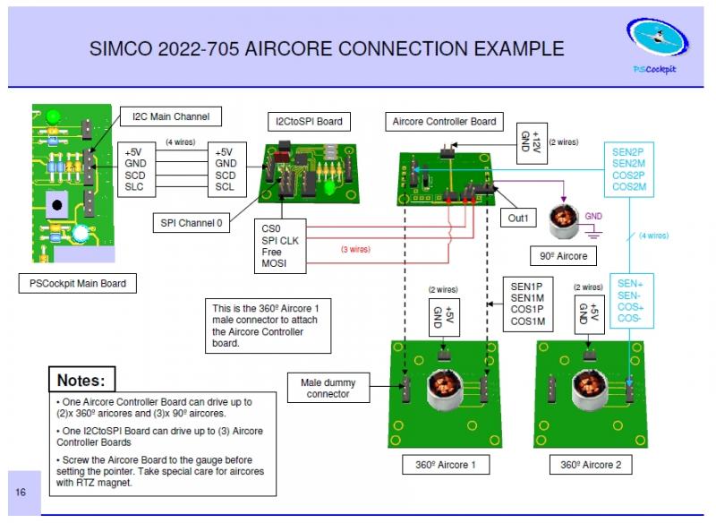
- I2CtoSPI pcb: This board is used to convert the I2C signal to SPI format. It must be connected to the I2C Main Channel of the PSCockpit Main Board to the Aircore Controller board:
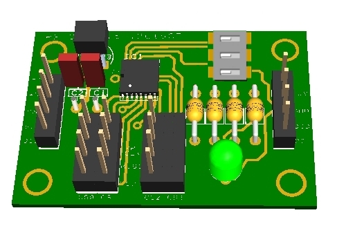
- Aircore Controller pcb: This board receives the SPI signal and drives (2) x 360º aircores plus (3) x 90º aircores. It must be connected to the I2CtoSPI board and to the Aircore pcb:
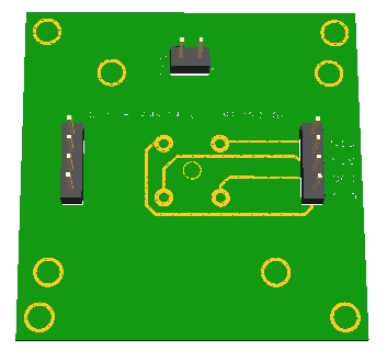
- Aircore pcb: This board supports the aircore and can be attached to your gauge. It must be connected to the Aircore Controller pcb:
The detail description of each board and the general overview of the system can be found in the PSCockpit System Quick Guide v2, which can be downloaded at http://www.mediafire.com/view/o7k6hvkt0y671iq/QuickGuideV2.pdf
Step 1: Placing your aircore in the Aircore pcb
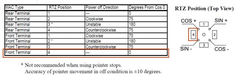
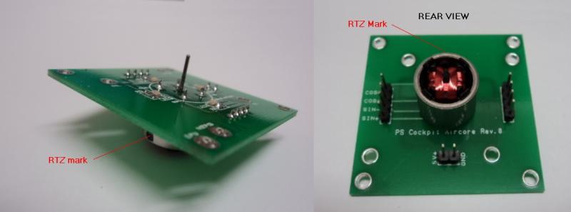
The supplied Simco 2022-705 aircores have terminals on the front and have a Return to Zero magnets (RTZ option). This option allows the aircore to return to zero position when power is deactivated. You must, then, find the correct position of the aircore motor in the aricore pcb in order to match the 0 physical position to the 0 electrical position, otherwise, once configured, the needle will point to other value of your gauge when power is off.
So, according to the Simco manual, the RTZ has to be located between cos+ and sen – terminals:
You will find a black mark on your aircore where the RTZ magnet is located:
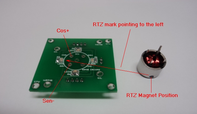
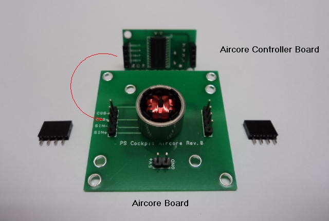
And the final assembly:
Step 2: Attaching the Aircore Controller Board to the Aircore Board:
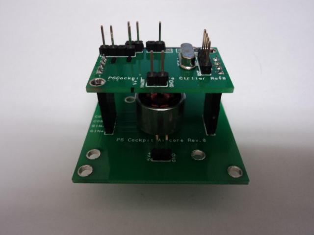
As the aircore body height is larger than the connectors, you will need two additional connectors which will act like spacers. Look for the correct position of the Aircore Controller board:
Aircore Controller Board attached to the Aircore board:
Step 3: Attaching the Aircore to your gauge
Use the holes of the Aircore board to fit it to your gauge plate. You will need some spacers to adjust the height of the aircore shaft:
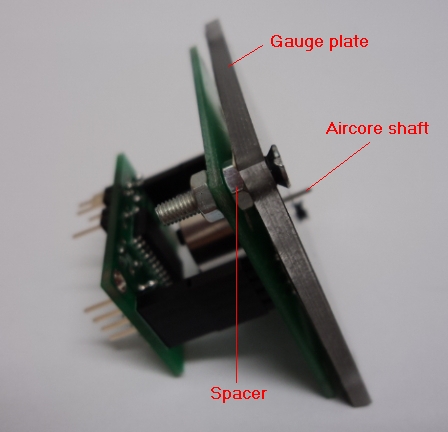
You can also cut the board carefully if it exceeds your gauge plate.
Now you can insert the pointing needle in to the aircore shaft pointing to the minimum value of your gauge scale:
Step 4: Connecting the Aircore Controller Board
Refer to the PSCockpit Guide v2 for details connections. Basically:
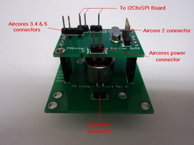
You can supply power to the Aircores power connector from 5V to 12V. With higher voltage the aircore will move faster and it will have more par but I found that 5V is more than enough for a weightless needle.
Step 5: Testing the aircore
Go to IOLayout page of the PSCockpit Software and select I2CtoSPI in the Expander address according the one selected in your board:
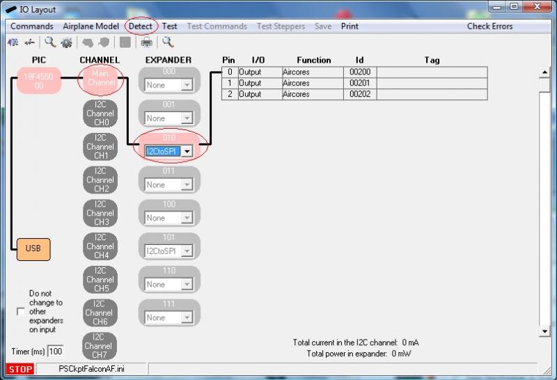
As the I2CtoSPI board can drive 3 Aircore Controller boards, you will see these 3 channels with different Ids. First Id (00200 in the picture) is the CS0 channel of your Aircore Controller board, second Id is the CS1 channel and third Id is the CS2 channel. CS3 channel of the I2CtoSPI board is not used and must remain unconnected.
Click on “Detect” and you will see the Expander in pink if the expander has been detected.
Click on “Test” and a “+” button will appear besides each of the Id channels. When you click on “+” button another screen will be opened showing the (2) x 360º and the (3) x 90º aircores connected to that channel. You can move any of the sliders and the aircore will move accordingly. You can also check the “Auto” check box to see the aircore moving continuously:
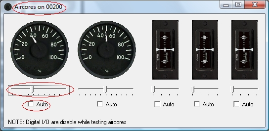
You can now power off your system and you will see the gauge needle returning to zero position.
Step 6: Configuring the Servos/PWM/Aircores
Since PSCockpit Software V 0.9.4 you can access directly to the Servos/PWM/Aircores configuration page. In this page you can configure the maximum/minimum scale of your gauge and the intermediate scales if your gauge has any.
To configure a desired aircore select the following parameters:
1. Select the aircore from the “Channel” display list. For each Id (SPI channel) you will see aircores from 0 to 4.
2. Select the sim value you want to be displayed on your gauge in the “Magnitude” display list.
3. Check the “Active” checkbox to enable the gauge.
4. Select the desire “Speed” of your gauge. Using the SSC-32 board for servos, this value will determine the microseconds will take the servo to go from one position to another. For the rest of the systems, aircores and servos with the Adafruit board, it is used to limit the minimum change of the variable to be sent to the gauge.
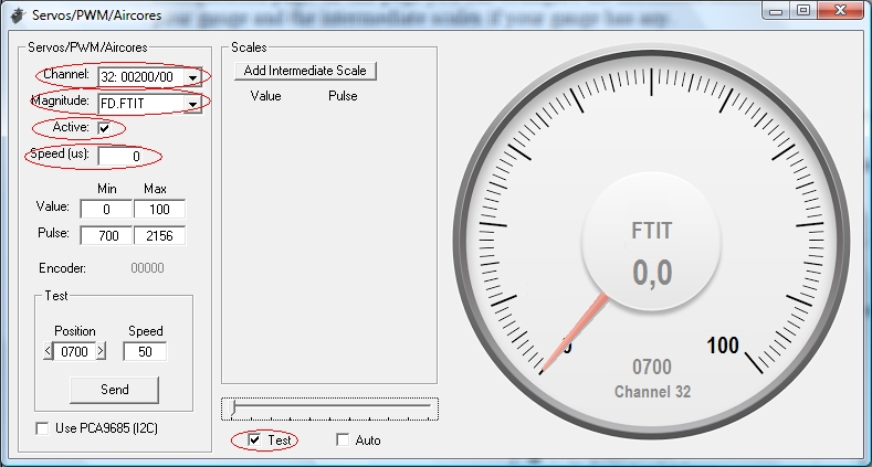
If you check the “Test” checkbox you can use the slider to move the selected gauge.
The first thing to do now is to find the lower and upper positions of your gauge and look what the pulses are the ones that match those positions. Move the slider (with the “Test” checkbox marked) to move your gauge needle until the lower value of your gauge is reached. The slider can be moved precisely with the left and right arrows of your keyboard once the slider is selected with your mouse. You will note that the “Position” value of the “Test” frame will change its value. When the gauge needle is in its lower position, this value has to be put in the Min Pulse box. Also put the minimum value of the gauge in the Min Value box:

To find the upper position of the gauge repeat this procedure by moving the slider and put the values in the Max Value and Max Pulse boxes:
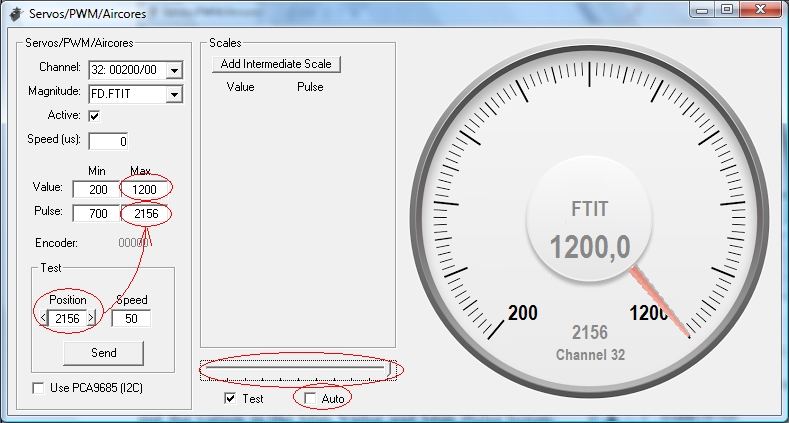
You can test your gauge by checking the “Auto” checkbox. You will see the gauge needle moving from the lower to upper positions without exceeding any of them. The “Speed” value of the Test frame is the amount added to the position, so you can reduce to a minimum of 10 to see your gauge moving smoothly.
Step 7: Adding intermediate scales to your gauge
If your gauge has different scales, you can add them easily by clicking on the “Add Intermediate Scale” button. Two text boxes will appear where you have to put the value and the pulse that correspond to that intermediate scale. Repeat the above procedure by moving the slider until the gauge needle is pointing to the intermediate scale value.
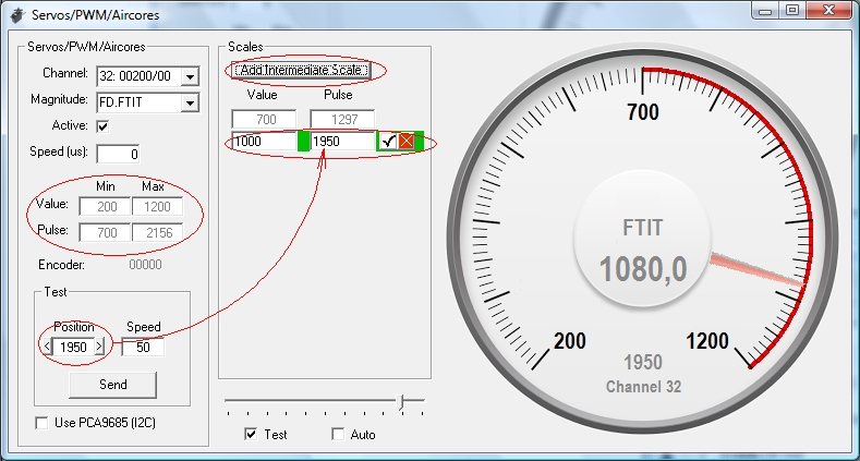
When any intermediate scale is added the minimum and maximum gauge values and pulses are disabled and can not be changed. To change these values you will have to remove the intermediate scales.
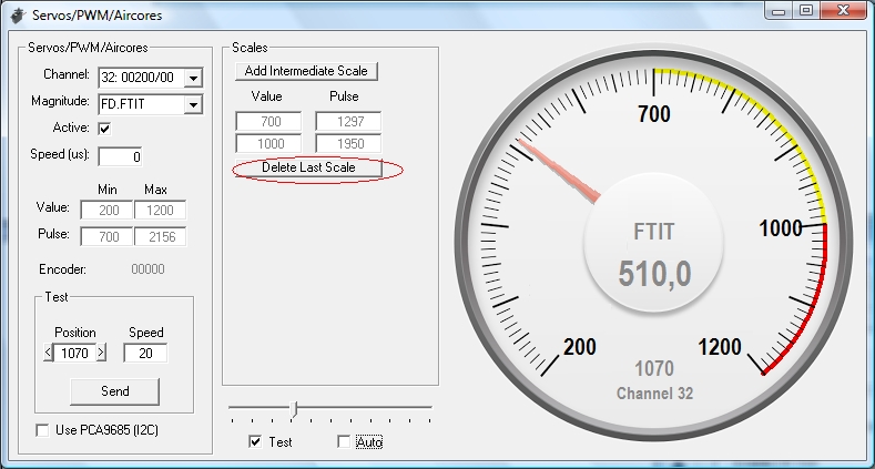
If you test your gauge now by selecting the “Auto” checkbox, you will see the gauge needle moving around the scales with different speeds.
Your aircore is now configured and you can use it with your favourite sim in Run mode of the PSCockpit Software.
One last consideration:
If you see your gauges moving a little jerky you can adjust them by setting the speed to 0 and resetting the timers on the “USB timers” page of the PSCockpit Software: try 10 ms for the “Sim data” timer and 0 for the “Between cycles” timer. Be aware that this will influence some other elements like encoders and/or 8x4 matrixes, so you will have to find the correct compromised values.
Regards,
Shep
Basically, the system consists of 3 different boards:
- I2CtoSPI pcb: This board is used to convert the I2C signal to SPI format. It must be connected to the I2C Main Channel of the PSCockpit Main Board to the Aircore Controller board:
- Aircore Controller pcb: This board receives the SPI signal and drives (2) x 360º aircores plus (3) x 90º aircores. It must be connected to the I2CtoSPI board and to the Aircore pcb:
- Aircore pcb: This board supports the aircore and can be attached to your gauge. It must be connected to the Aircore Controller pcb:
The detail description of each board and the general overview of the system can be found in the PSCockpit System Quick Guide v2, which can be downloaded at http://www.mediafire.com/view/o7k6hvkt0y671iq/QuickGuideV2.pdf
Step 1: Placing your aircore in the Aircore pcb
The supplied Simco 2022-705 aircores have terminals on the front and have a Return to Zero magnets (RTZ option). This option allows the aircore to return to zero position when power is deactivated. You must, then, find the correct position of the aircore motor in the aricore pcb in order to match the 0 physical position to the 0 electrical position, otherwise, once configured, the needle will point to other value of your gauge when power is off.
So, according to the Simco manual, the RTZ has to be located between cos+ and sen – terminals:
You will find a black mark on your aircore where the RTZ magnet is located:
And the final assembly:
Step 2: Attaching the Aircore Controller Board to the Aircore Board:
As the aircore body height is larger than the connectors, you will need two additional connectors which will act like spacers. Look for the correct position of the Aircore Controller board:
Aircore Controller Board attached to the Aircore board:
Step 3: Attaching the Aircore to your gauge
Use the holes of the Aircore board to fit it to your gauge plate. You will need some spacers to adjust the height of the aircore shaft:
You can also cut the board carefully if it exceeds your gauge plate.
Now you can insert the pointing needle in to the aircore shaft pointing to the minimum value of your gauge scale:
Step 4: Connecting the Aircore Controller Board
Refer to the PSCockpit Guide v2 for details connections. Basically:
You can supply power to the Aircores power connector from 5V to 12V. With higher voltage the aircore will move faster and it will have more par but I found that 5V is more than enough for a weightless needle.
Step 5: Testing the aircore
Go to IOLayout page of the PSCockpit Software and select I2CtoSPI in the Expander address according the one selected in your board:
As the I2CtoSPI board can drive 3 Aircore Controller boards, you will see these 3 channels with different Ids. First Id (00200 in the picture) is the CS0 channel of your Aircore Controller board, second Id is the CS1 channel and third Id is the CS2 channel. CS3 channel of the I2CtoSPI board is not used and must remain unconnected.
Click on “Detect” and you will see the Expander in pink if the expander has been detected.
Click on “Test” and a “+” button will appear besides each of the Id channels. When you click on “+” button another screen will be opened showing the (2) x 360º and the (3) x 90º aircores connected to that channel. You can move any of the sliders and the aircore will move accordingly. You can also check the “Auto” check box to see the aircore moving continuously:
You can now power off your system and you will see the gauge needle returning to zero position.
Step 6: Configuring the Servos/PWM/Aircores
Since PSCockpit Software V 0.9.4 you can access directly to the Servos/PWM/Aircores configuration page. In this page you can configure the maximum/minimum scale of your gauge and the intermediate scales if your gauge has any.
To configure a desired aircore select the following parameters:
1. Select the aircore from the “Channel” display list. For each Id (SPI channel) you will see aircores from 0 to 4.
2. Select the sim value you want to be displayed on your gauge in the “Magnitude” display list.
3. Check the “Active” checkbox to enable the gauge.
4. Select the desire “Speed” of your gauge. Using the SSC-32 board for servos, this value will determine the microseconds will take the servo to go from one position to another. For the rest of the systems, aircores and servos with the Adafruit board, it is used to limit the minimum change of the variable to be sent to the gauge.
If you check the “Test” checkbox you can use the slider to move the selected gauge.
The first thing to do now is to find the lower and upper positions of your gauge and look what the pulses are the ones that match those positions. Move the slider (with the “Test” checkbox marked) to move your gauge needle until the lower value of your gauge is reached. The slider can be moved precisely with the left and right arrows of your keyboard once the slider is selected with your mouse. You will note that the “Position” value of the “Test” frame will change its value. When the gauge needle is in its lower position, this value has to be put in the Min Pulse box. Also put the minimum value of the gauge in the Min Value box:
To find the upper position of the gauge repeat this procedure by moving the slider and put the values in the Max Value and Max Pulse boxes:
You can test your gauge by checking the “Auto” checkbox. You will see the gauge needle moving from the lower to upper positions without exceeding any of them. The “Speed” value of the Test frame is the amount added to the position, so you can reduce to a minimum of 10 to see your gauge moving smoothly.
Step 7: Adding intermediate scales to your gauge
If your gauge has different scales, you can add them easily by clicking on the “Add Intermediate Scale” button. Two text boxes will appear where you have to put the value and the pulse that correspond to that intermediate scale. Repeat the above procedure by moving the slider until the gauge needle is pointing to the intermediate scale value.
When any intermediate scale is added the minimum and maximum gauge values and pulses are disabled and can not be changed. To change these values you will have to remove the intermediate scales.
If you test your gauge now by selecting the “Auto” checkbox, you will see the gauge needle moving around the scales with different speeds.
Your aircore is now configured and you can use it with your favourite sim in Run mode of the PSCockpit Software.
One last consideration:
If you see your gauges moving a little jerky you can adjust them by setting the speed to 0 and resetting the timers on the “USB timers” page of the PSCockpit Software: try 10 ms for the “Sim data” timer and 0 for the “Between cycles” timer. Be aware that this will influence some other elements like encoders and/or 8x4 matrixes, so you will have to find the correct compromised values.
Regards,
Shep
Saturday, May 10, 2014
New version of the PSCockpit System firmware
To resolve a bug with the potentiometers full range connected to the Main Board, I have issued a new firmware version 1.5.2
You can download at:
http://www.mediafire.com/download/mbbalaimytpamsm/PSFirmUpdtv152.rar
Regards,
Shep
You can download at:
http://www.mediafire.com/download/mbbalaimytpamsm/PSFirmUpdtv152.rar
Regards,
Shep
Sunday, March 23, 2014
PSCockpit Quick Guide Version 2
PSCockpit Quick Guide Version 2 now available with the new boards added.
You can download at: http://www.mediafire.com/view/o7k6hvkt0y671iq/QuickGuideV2.pdf
Regards,
Shep
You can download at: http://www.mediafire.com/view/o7k6hvkt0y671iq/QuickGuideV2.pdf
Regards,
Shep
Friday, February 21, 2014
PSCockpit Software (v 0.9.6) and Firmware (v 1.5.1) update
Hi everybody,
I have updated the PSCockpit software to v.0.9.6 to solve the problem with the Adafruit board.
Sorry, one of my fingers deleted by mistake one line of the code in the last version.
Don't worry, I have cut that finger out of my hand....
Thanks to Dragun for his help on resolving the issue
You can download the PSCockpit Sofware v.0.9.6 (WIP) at:
http://www.mediafire.com/download/ff2fbfzvclumcph/PSCockpitV096.rar
Just unrar and move the PSCockpit.exe file to your PSCockpit folder.
Also you can find the last version of the firmware (v 1.5.1) at:
http://www.mediafire.com/download/dc553f6xymedrde/PSFirmUpdtv151.rar
PSCockpit System Firmware v.1.5.1 Changelog:
- Added I2CtoSPI board controller
- Added Aircores board controller
- Added OLED display configuration
- Corrected a reverse video OLED display bug
Regards,
Shep
Sunday, February 16, 2014
PSCockpit Software Update v 0.9.5 (WIP)
This version of the PSCockpit software correct the following bugs:
- Lines in the Layout aren't deleted.
- Adafruit servos.
You can download the new version v.0.9.5 (WIP) at: http://www.mediafire.com/download/h3ahu12606t7m9s/PSCockpitV095.rar
Just unrar and copy it to the PSCockpit directory.
Regards,
Shep
- Lines in the Layout aren't deleted.
- Adafruit servos.
You can download the new version v.0.9.5 (WIP) at: http://www.mediafire.com/download/h3ahu12606t7m9s/PSCockpitV095.rar
Just unrar and copy it to the PSCockpit directory.
Regards,
Shep
Sunday, January 26, 2014
New PSCockpit Boards
Hello everybody,
After several days of hard work, I am glad to announce that the aircores are up and running!!
Nevertheless, I still have to work on the software to adapt the values extracted from the sim and the scales of the gauges to the special way they work and test them on duty.
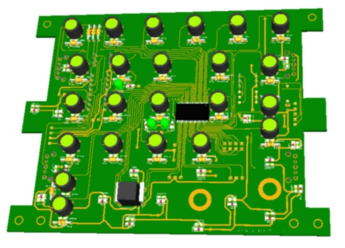
Some pictures of the new boards:
ICP:
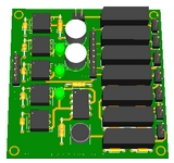
 Vib motors:
Regards,
Shep
After several days of hard work, I am glad to announce that the aircores are up and running!!
Nevertheless, I still have to work on the software to adapt the values extracted from the sim and the scales of the gauges to the special way they work and test them on duty.
Some pictures of the new boards:
ICP:
Regards,
Shep
Monday, January 6, 2014
PSCockpit Software Version 0.9.4 (WIP)
Happy New
Year for everybody!!
This version
is still a WIP version with much new functionality not totally tested, but I'm
publishing it to solve some bugs detected with the Adafruit board and to
improve the encoder’s functionality.
CHANGELOG V
0.9.4 (WIP)
======================
- Corrected
an error sending Adafruit PWM values (Thanks Cester!!)- Added option to sync sim with cockpit switches (PSCockpit page)
- Lights, servos and 7 Segment Displays, extracted from the sim can be seen in the Airplane Model
- Servos/PWM/Aircore scales (Airplane Model)
- Airplane selection (PSCockpit Menu)
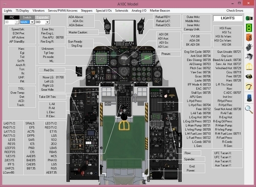
- A10C Model implemented (Airplane Model)
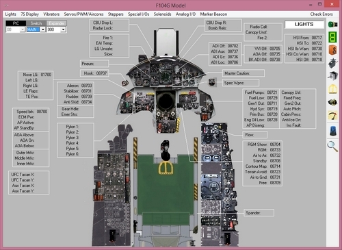
- F104G Model implemented (Airplane model)
- Corrected USB driver to plug/unplug and switch on/off the board with the PSCockpit software running
- Implemented Error handling to avoid errors when entering in AWACS (BMS)
- Added wave files for Bass Shakers and sound device selection (Vibration Effects page )
- Analog outputs implemented (F16 Model-AnalogI/Os page)
- Print commands (Commands page)
- Added SLG2016 driver for 2 and
- Added DED and PFL brightness inputs from pots (F16 Model-Pots page)
- POWER_OFF bit implemented in F16 Model (Special I/Os page)
- Added leds to DX Joystick pushbuttons when active in Joystick (Assignments page)
- Added Inverse checkbox for the encoders (Commands-Encoders page)
- Encoders routine improved
You can
download it HERE.
Regards,
Shep
Saturday, January 4, 2014
New Version of PSUDP Updated for Android 4.0
PSUdp extracts the flight data from Open Falcon, Falcon AF and Falcon BMS flight simulators acting like a server and send this data to an android mobile device running the client application PS Gauges trough the TCP/UDP net protocol.
- Updated PSGauges.apk for Android 4.0
- Fixed the problem with the local IP address by using the WIFI IP address.
- Update for BMS 4.32 up 6.
You can download the installation file here: PSUDPv09
Installation notes:
- Unrar the file
- Install PS UDP in your computer with PSUdpSetUp.exe
- Install PSGauges.apk in all your favorite android devices
- Read HelpV09.txt!!
- Enjoy
Regards,
Shep
PS UDP Falcon supports 5 clients connected at the same time so you can use five different android devices. Three of them are used for flight data, one for the left MFD, one for the right MFD and one for the HUD.
PS Gauges client application needs Android 4.0
PS Gauges can display in your mobile device the following instruments: RPM, RWR, HSI, DED, PFL, ADI, VVI, AOA, ASI, ALT, CMPSS, CP, FFI, FI, ICP, LMFD, HUD and RMFD.
- Updated PSGauges.apk for Android 4.0
- Fixed the problem with the local IP address by using the WIFI IP address.
- Update for BMS 4.32 up 6.
You can download the installation file here: PSUDPv09
Installation notes:
- Unrar the file
- Install PS UDP in your computer with PSUdpSetUp.exe
- Install PSGauges.apk in all your favorite android devices
- Read HelpV09.txt!!
- Enjoy
Regards,
Shep
Thursday, December 26, 2013
Work in Progress of the PSCockpit Software
I’m working on the new features of the PSCockpit software:
- A10C Model:
- F104G Model:
- Servos/PWM/Aircores scales:
Regards,
Shep
- A10C Model:
- F104G Model:
- Servos/PWM/Aircores scales:
Regards,
Shep
Sunday, November 17, 2013
PSCockpit Welcomes DCS A10C Supporters!!
A10C UFC BOARD
Designed with (1) 40 I/O chip that can be connected to the digital I/O I2C channel of the PSCockpit system. It comes with corresponding elements (resistors, connectors, …) to work with 5V and a selectable mini-switch to select the desire I2C addresses.
For those of you that would like to use the Korry 318 "Caution" switch, the pcb is designed with room enough to make the cut-out of the switch and a connector to wire the switch.
Also included are the following components:
- (35) Mini switches with internal leds for pushbutton backlight. The leds are connected to the illumination circuit to allow “dimmering”.
- (21) SMD leds for lettering backlight.
- (1) frontal led
You will find the following elements in the backside:
- (1) Connector for backlight illumination.
- (1) Connector for digital I/O I2C channel,
- (1) Miniswitch to select digital I2C channel address
- (1) Connector for 5 free digital I/O of the 40 I/O board. You can use them to light the frontal led and/or to connect other switches, pushbuttons
- (1) One connector for the Korry 318 "Caution" switch
To complete the UFC you will have to add by yourself the following elements:
- UFC case
- Pushbutton covers
Please check the following dimensions for the UFC case.
You can download the file from:
http://www.mediafire.com/view/bujvl015hcd7e3q/UFCMetric.pdf
A10C CDU BOARD

Designed with (2) 40 I/O chip that can be connected to the digital I/O I2C channel of the PSCockpit system. It comes with corresponding elements (resistors, connectors, …) to work with 5V and (2) selectable mini-switch to select the desire I2C addresses.
Also included are the following components:
- (66) Mini switches with internal leds for pushbutton backlight. The leds are connected to the illumination circuit to allow “dimmering”.
- (1) frontal led
You will find the following elements in the backside:
- (2) Connectors for backlight illumination.
- (2) Connector for digital I/O I2C channel in daisy chain
- (2) Miniswitchs to select digital I2C channel addresses
- (2) Connector for 10 free digital I/O of the 40 I/O boards. You can use them to light the frontal led and/or to connect other switches, pushbuttons
To complete the CDU you will have to add by yourself the following elements:
- CDU case
- Pushbutton covers.
- CDU display
Dimensions to follow.
Regards,
Shep
Designed with (1) 40 I/O chip that can be connected to the digital I/O I2C channel of the PSCockpit system. It comes with corresponding elements (resistors, connectors, …) to work with 5V and a selectable mini-switch to select the desire I2C addresses.
For those of you that would like to use the Korry 318 "Caution" switch, the pcb is designed with room enough to make the cut-out of the switch and a connector to wire the switch.
Also included are the following components:
- (35) Mini switches with internal leds for pushbutton backlight. The leds are connected to the illumination circuit to allow “dimmering”.
- (21) SMD leds for lettering backlight.
- (1) frontal led
You will find the following elements in the backside:
- (1) Connector for backlight illumination.
- (1) Connector for digital I/O I2C channel,
- (1) Miniswitch to select digital I2C channel address
- (1) Connector for 5 free digital I/O of the 40 I/O board. You can use them to light the frontal led and/or to connect other switches, pushbuttons
- (1) One connector for the Korry 318 "Caution" switch
To complete the UFC you will have to add by yourself the following elements:
- UFC case
- Pushbutton covers
Please check the following dimensions for the UFC case.
You can download the file from:
http://www.mediafire.com/view/bujvl015hcd7e3q/UFCMetric.pdf
A10C CDU BOARD
Designed with (2) 40 I/O chip that can be connected to the digital I/O I2C channel of the PSCockpit system. It comes with corresponding elements (resistors, connectors, …) to work with 5V and (2) selectable mini-switch to select the desire I2C addresses.
Also included are the following components:
- (66) Mini switches with internal leds for pushbutton backlight. The leds are connected to the illumination circuit to allow “dimmering”.
- (1) frontal led
You will find the following elements in the backside:
- (2) Connectors for backlight illumination.
- (2) Connector for digital I/O I2C channel in daisy chain
- (2) Miniswitchs to select digital I2C channel addresses
- (2) Connector for 10 free digital I/O of the 40 I/O boards. You can use them to light the frontal led and/or to connect other switches, pushbuttons
To complete the CDU you will have to add by yourself the following elements:
- CDU case
- Pushbutton covers.
- CDU display
Dimensions to follow.
Regards,
Shep
Sunday, November 3, 2013
HOW to Use POWER_OFF Bit
When you energize your pit with the PSCockpit Sytem, some others elements, like 7 segment displays, are also turned on, so, if you enter a mission in Ramp Start the displays will be showing zeros while the cockpit in the sim isn’t still energized.
To give more reality to our pits we can now take advantage of the POWER_OFF bit of the BMS sim (thanks BMS team!!).
You can activate this function by selecting the “Use Power_OFF bit” checkbox in the F-16 Model page under Special I/Os:

By selecting this function the PSCockpit Software will do the following:
- Remove any text in the DED and PFL display
- Activate all the POWER_OFF outputs of the F-16 Model (see picture above)
- More to come….
How to use the Power_OFF outputs in 7 Seg. Displays boards
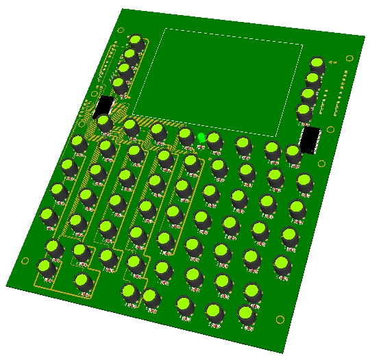
To use this functionality with the 7 seg. displays boards, you will have to define, first, one output in the IOLayout. I have selected one of the 40 I/O board that I have in the CMDS panel to use it with the 7 seg. display board of the CMDS digits:
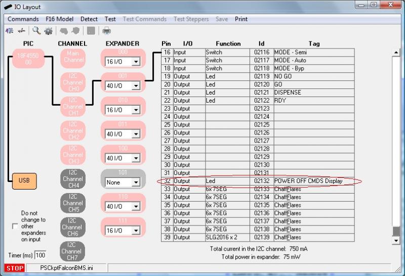
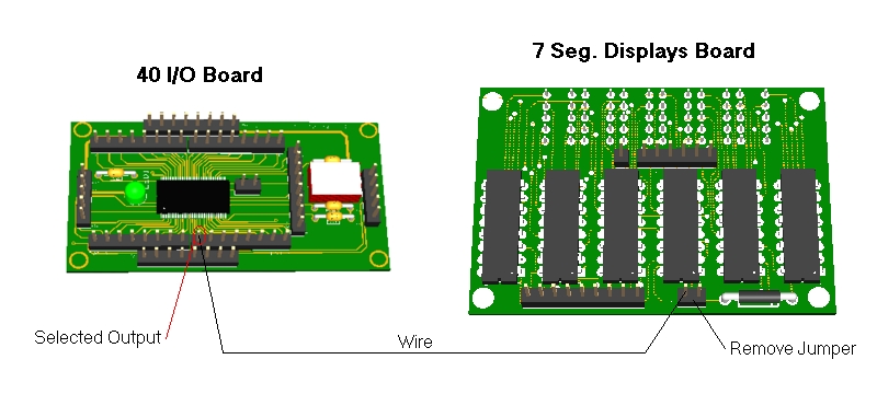
You will have to remove the jumper of the 7 Seg. Displays board and connect one wire from the pin marked as PWM to the selected output of the 40I/O board:
The last step is to select this output as one of the Power_OFF outputs in the F16 Model page (see first picture).
By the way, this PWM input of the 7 Seg. Displays Board can be connected to a PWM output to control the brightness of the displays.
(Added on Dec., 10th)
The Power Off bits have been updated for CMDS and UHF panels.
Now, this is the way PSCockpit works with the Power_Off Bits:
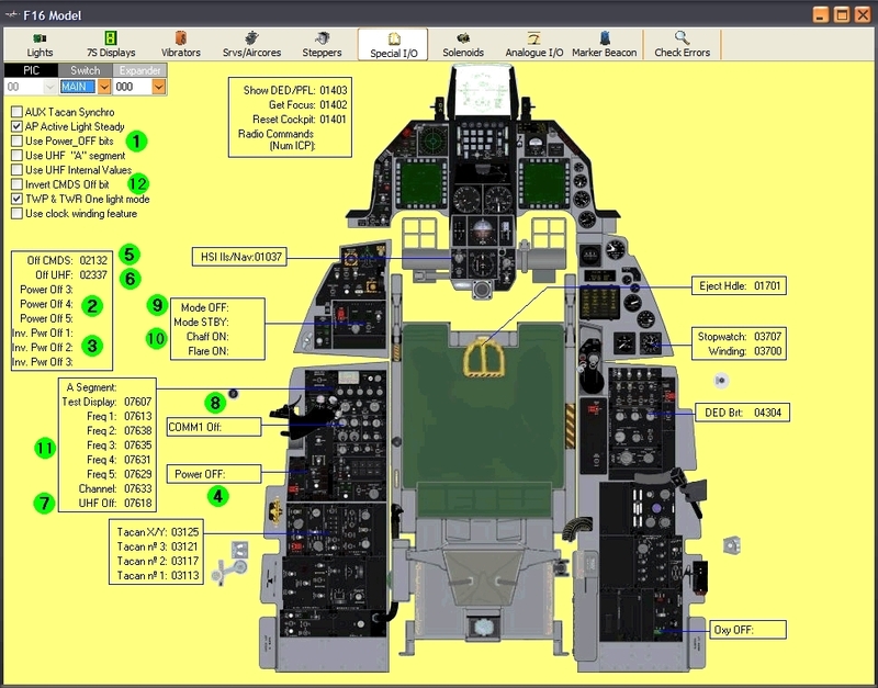
a) The “Use Power_OFF bits” checkbox (number 1), when checked, allows the software to use the Power Off bits (number 2), Inverted Power Off bits (number 3), OFF CMDS (number 5) and OFF UHF (number 6).
b) Power Off outputs (number 2) will be set to HIGH when the sim is in Power Off condition and Inverted Power Off outputs (number 3) will be set to LOW when the sim is in Power Off condition and vice versa when the sim is not in Power Off condition. Some devices will need a HIGH signal and some others may need a LOW signal.
c) The Power Off condition of the sim is an internal signal. In BMS, it comes from the Shared Memory, but, as some other sims (as old versions of BMS), do not have the internal Power OFF value, you can use the function with the Power Off switch of the Elec panel (number 4). This switch must be HIGH when Power Off condition.
d) There are specific Power OFF bits for the CMDS (number 5) and UHF panels (number 6) because some others conditions have been added as below explanations.
e) Off CMDS output (number 5) will be set to HIGH (display OFF) when one of the following inputs/signal are HIGH:
- In BMS: CMDS Off (from BMS Share Memory)
- In Falcon AF: Selector Mode OFF (number 9). Also in this sim, the rest of the inputs (number 10) are used for CMDS displays
- “Invert CMDS Off Bit” checkbox (number 12), when checked, inverts the output Off CMDS.
f) Off UHF output (number 6) will be set to HIGH (display OFF) when one of the following inputs/signals are HIGH:
- Power Off (from BMS shared memory)
- UHF Selector Mode OFF (number 7)
- Selector COMM1 Off (number 8)
- All other values for UHF (number 11) are used only to use internal frequency. It is used in other sims where the frequency is not available.
Regards,
Shep
To give more reality to our pits we can now take advantage of the POWER_OFF bit of the BMS sim (thanks BMS team!!).
You can activate this function by selecting the “Use Power_OFF bit” checkbox in the F-16 Model page under Special I/Os:
- Remove any text in the DED and PFL display
- Activate all the POWER_OFF outputs of the F-16 Model (see picture above)
- More to come….
How to use the Power_OFF outputs in 7 Seg. Displays boards
To use this functionality with the 7 seg. displays boards, you will have to define, first, one output in the IOLayout. I have selected one of the 40 I/O board that I have in the CMDS panel to use it with the 7 seg. display board of the CMDS digits:
By the way, this PWM input of the 7 Seg. Displays Board can be connected to a PWM output to control the brightness of the displays.
(Added on Dec., 10th)
The Power Off bits have been updated for CMDS and UHF panels.
Now, this is the way PSCockpit works with the Power_Off Bits:
a) The “Use Power_OFF bits” checkbox (number 1), when checked, allows the software to use the Power Off bits (number 2), Inverted Power Off bits (number 3), OFF CMDS (number 5) and OFF UHF (number 6).
b) Power Off outputs (number 2) will be set to HIGH when the sim is in Power Off condition and Inverted Power Off outputs (number 3) will be set to LOW when the sim is in Power Off condition and vice versa when the sim is not in Power Off condition. Some devices will need a HIGH signal and some others may need a LOW signal.
c) The Power Off condition of the sim is an internal signal. In BMS, it comes from the Shared Memory, but, as some other sims (as old versions of BMS), do not have the internal Power OFF value, you can use the function with the Power Off switch of the Elec panel (number 4). This switch must be HIGH when Power Off condition.
d) There are specific Power OFF bits for the CMDS (number 5) and UHF panels (number 6) because some others conditions have been added as below explanations.
e) Off CMDS output (number 5) will be set to HIGH (display OFF) when one of the following inputs/signal are HIGH:
- In BMS: CMDS Off (from BMS Share Memory)
- In Falcon AF: Selector Mode OFF (number 9). Also in this sim, the rest of the inputs (number 10) are used for CMDS displays
- “Invert CMDS Off Bit” checkbox (number 12), when checked, inverts the output Off CMDS.
f) Off UHF output (number 6) will be set to HIGH (display OFF) when one of the following inputs/signals are HIGH:
- Power Off (from BMS shared memory)
- UHF Selector Mode OFF (number 7)
- Selector COMM1 Off (number 8)
- All other values for UHF (number 11) are used only to use internal frequency. It is used in other sims where the frequency is not available.
Regards,
Shep
Friday, October 25, 2013
HOW to VIBRATORS/BASS SHAKERS
The PSCockpit Software is able to drive up to 6 vibration motors with 4 different speeds and/or send .wav files to your bass shaker within your favourite sim.
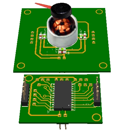
Vibration motors
The vibration motors are driven by means of 6 on/off signals and 4 speed signals. With this configuration you can use the vibration motor pcb.
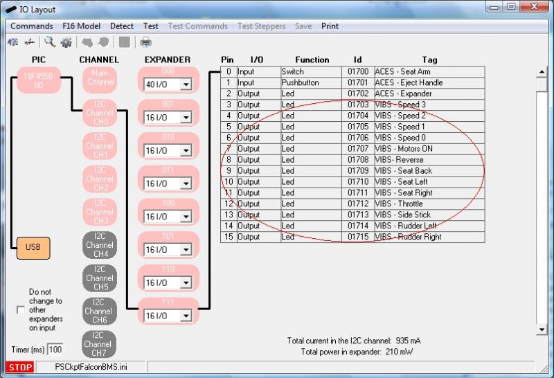
To configure the vibration motors in the PSCockpit Software go to IOLayout and select Leds as ouputs. You will have to define the following outputs:
- (4) for speed signals
- (1) for general ON signal
- (x) for the individual ON/OFF motor signals
You can test your outputs, as usual, by clicking on “Test” command and activating the proper checkbox.
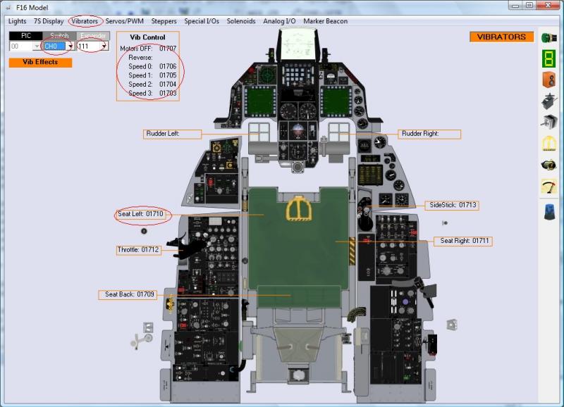
Now that we have defined the outputs, we have to tell the PSCockpit Software the function of each output. This is done in the “F16 Model” page, under the tab “Vibrators”. Just select in each position the correct Id of the output previously introduced:
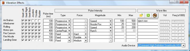
The next step is to select the behaviour of the vibrator motors depending on the variables of the sim. To do this go to “Vibs Effects” from this page or from the Main Page of the PSCockpit Software. The following screen will be opened:
The actual variables of the sim that can be programmed are the following:
- Air brakes: becomes active when the airbrakes are deployed
- Afterburner: becomes active when the afterburner is reached
- Rolling: becomes active when you are on the ground
- Motor rpm: self explanatory.
- Fire Cannon: becomes active when you push fire cannon button of your joystick.
- Fire Missile: becomes active when you push fire missile button of your joystick.
- Landing Gear: becomes active while the landing gear is in extension/retraction movement.
Select in each checkbox what motors you would like to activate when a sim variable becomes active.
To define the pulse intensity you can define the following variables:
Type:
- Fixed: The pulse intensity is always the same.
- Progressive: The pulse intensity begins from Min. to Max. defined later
- Center peak: The pulse reaches the highest intensity in the middle of Min. and Max.
Force. If you have selected a fixed type, you can establish the force level:
- Off: No motor will be activated
- Slight: Speed 0 will be activated.
- Rumble: Speed 1 will be activated.
- Medium: Speed 2 will be activated.
- Hard: Speed 3 will be activated.
Magnitude: If you have selected a Center Peak or Progressive type, you can select one of the following sim varables:
- RMP%
- Speed
- RMPxSpeed
- Nozzle Pos
- Fuel Flow
Min. and Max: The values of these variables should match the selected magnitude variable and also will define the interval when the motors will be active.
Depending on all the above values the software will determine what motor speed output will be activated.
To assign the joystick buttons for cannon and missile fire go to “Joystick” page and assign the desire buttons:

Two examples:
- I would like to feel the runaway while taking off or landing, so I have selected the Rolling variable to activate all the vibrators in a progressive manner, depending on the speed from 20 to 200 knots. In this way as the speed on the runaways increases the vibration increase and will stop when the speed reaches 200 knots which will be when the wheels leave the runaway.
- While on Ramp Start, I would like to feel how the motor begins to turn, so I have selected the Motor RPM to activate all the vibrators in a center peak manner, depending on RPM% from 10 to 60% rpm. In this way, when I push on the Start 1 switch, the vibrators will begin in slight mode and when I move the throttle forward I will feel how the vibration increases up to 30% rpm and will decrease until 60% when it supposed the motor reaches the nominal rpm. Just like starting the motor of you car!
I have to tell you that these effects are simply amazing!!
Wave files
The way the wave files are treated is the same as the vibrator motors but the software changes the volume of the sound.
To select a wave file put the cursor in the desire text box and click on the Open File icon. Then select the .wav file. They must be saved on your PSCockpit directory.
To test a .wav file, put the cursor on the desired text box and click on the Play icon.
You can change the volume and the frequency of the .wav file to adjust anyhow your bass shaker. The PSCockpit software will change the volume from this selected volume.
If you have more than one Audio device you can select in which one the .wav will be sent to by selecting the correct one in the display list “Audio Device”.
Be aware that in a PC the back and front sound outputs are handled by the same audio device, but you can use your back/front sound output for bass shakers and have a USB headphones for team speak.
Regards,
Shep
Vibration motors
The vibration motors are driven by means of 6 on/off signals and 4 speed signals. With this configuration you can use the vibration motor pcb.
To configure the vibration motors in the PSCockpit Software go to IOLayout and select Leds as ouputs. You will have to define the following outputs:
- (4) for speed signals
- (1) for general ON signal
- (x) for the individual ON/OFF motor signals
You can test your outputs, as usual, by clicking on “Test” command and activating the proper checkbox.
Now that we have defined the outputs, we have to tell the PSCockpit Software the function of each output. This is done in the “F16 Model” page, under the tab “Vibrators”. Just select in each position the correct Id of the output previously introduced:
The next step is to select the behaviour of the vibrator motors depending on the variables of the sim. To do this go to “Vibs Effects” from this page or from the Main Page of the PSCockpit Software. The following screen will be opened:
The actual variables of the sim that can be programmed are the following:
- Air brakes: becomes active when the airbrakes are deployed
- Afterburner: becomes active when the afterburner is reached
- Rolling: becomes active when you are on the ground
- Motor rpm: self explanatory.
- Fire Cannon: becomes active when you push fire cannon button of your joystick.
- Fire Missile: becomes active when you push fire missile button of your joystick.
- Landing Gear: becomes active while the landing gear is in extension/retraction movement.
Select in each checkbox what motors you would like to activate when a sim variable becomes active.
To define the pulse intensity you can define the following variables:
Type:
- Fixed: The pulse intensity is always the same.
- Progressive: The pulse intensity begins from Min. to Max. defined later
- Center peak: The pulse reaches the highest intensity in the middle of Min. and Max.
Force. If you have selected a fixed type, you can establish the force level:
- Off: No motor will be activated
- Slight: Speed 0 will be activated.
- Rumble: Speed 1 will be activated.
- Medium: Speed 2 will be activated.
- Hard: Speed 3 will be activated.
Magnitude: If you have selected a Center Peak or Progressive type, you can select one of the following sim varables:
- RMP%
- Speed
- RMPxSpeed
- Nozzle Pos
- Fuel Flow
Min. and Max: The values of these variables should match the selected magnitude variable and also will define the interval when the motors will be active.
Depending on all the above values the software will determine what motor speed output will be activated.
To assign the joystick buttons for cannon and missile fire go to “Joystick” page and assign the desire buttons:
Two examples:
- I would like to feel the runaway while taking off or landing, so I have selected the Rolling variable to activate all the vibrators in a progressive manner, depending on the speed from 20 to 200 knots. In this way as the speed on the runaways increases the vibration increase and will stop when the speed reaches 200 knots which will be when the wheels leave the runaway.
- While on Ramp Start, I would like to feel how the motor begins to turn, so I have selected the Motor RPM to activate all the vibrators in a center peak manner, depending on RPM% from 10 to 60% rpm. In this way, when I push on the Start 1 switch, the vibrators will begin in slight mode and when I move the throttle forward I will feel how the vibration increases up to 30% rpm and will decrease until 60% when it supposed the motor reaches the nominal rpm. Just like starting the motor of you car!
I have to tell you that these effects are simply amazing!!
Wave files
The way the wave files are treated is the same as the vibrator motors but the software changes the volume of the sound.
To select a wave file put the cursor in the desire text box and click on the Open File icon. Then select the .wav file. They must be saved on your PSCockpit directory.
To test a .wav file, put the cursor on the desired text box and click on the Play icon.
You can change the volume and the frequency of the .wav file to adjust anyhow your bass shaker. The PSCockpit software will change the volume from this selected volume.
If you have more than one Audio device you can select in which one the .wav will be sent to by selecting the correct one in the display list “Audio Device”.
Be aware that in a PC the back and front sound outputs are handled by the same audio device, but you can use your back/front sound output for bass shakers and have a USB headphones for team speak.
Regards,
Shep
Thursday, October 24, 2013
AIRCORES PCBs
More information about the aircore pcbs.
I have selected the chip MLX10407 from Melexis to drive the aircores. In fact, it is the only one with serial protocol I found in the electronic store. This chip is able to drive two 360º aircores and three 90º actuators, although these ones will be useless for our pits, maybe they can be used for roll trim and pitch trim indicators or maybe other instruments by means of a gear.
With this chip I have developed the Aircore Controller pcb.
To hold the aircore you can use your own board or the new Aircore PCB wich will fit in a 40x40 mm instrument. The Aircore Controller pcb can be attached at the bottom side of the Aircore board without any extra wiring by means of two connectors.
You can see both here:
 You can, then, wire the second aircore from the Aircore Controller pcb.
To drive the Aircore Controller you will also need the I2CtoSPI pcb. This board is able to drive up to 4 SPI devices and, apart of the aircores, can be used in the future to drive other SPI devices like, for example, the OLED display:
In this way, PSCockpit software will be able to drive up to 8 I2CtoSPI boards, which mean 34 Aircore controllers, which mean 68 (360º) aircores and 102 (90º) actuators.
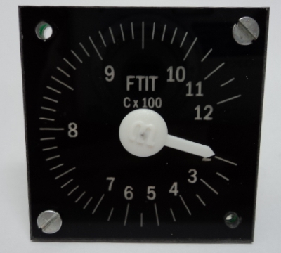
In summary, for the engine instruments (OIL, NOZ POS, RPM and FTIT) you will need one I2CtoSPI board and two Aircore Controller pcbs for full 360º aircores.
Hope you like it!!
More info about the ICP board to come.
Regards,
Shep
I have selected the chip MLX10407 from Melexis to drive the aircores. In fact, it is the only one with serial protocol I found in the electronic store. This chip is able to drive two 360º aircores and three 90º actuators, although these ones will be useless for our pits, maybe they can be used for roll trim and pitch trim indicators or maybe other instruments by means of a gear.
With this chip I have developed the Aircore Controller pcb.
To hold the aircore you can use your own board or the new Aircore PCB wich will fit in a 40x40 mm instrument. The Aircore Controller pcb can be attached at the bottom side of the Aircore board without any extra wiring by means of two connectors.
You can see both here:
To drive the Aircore Controller you will also need the I2CtoSPI pcb. This board is able to drive up to 4 SPI devices and, apart of the aircores, can be used in the future to drive other SPI devices like, for example, the OLED display:
In this way, PSCockpit software will be able to drive up to 8 I2CtoSPI boards, which mean 34 Aircore controllers, which mean 68 (360º) aircores and 102 (90º) actuators.
In summary, for the engine instruments (OIL, NOZ POS, RPM and FTIT) you will need one I2CtoSPI board and two Aircore Controller pcbs for full 360º aircores.
Hope you like it!!
More info about the ICP board to come.
Regards,
Shep
Subscribe to:
Posts (Atom)