Implementing Aircores in PSCockpit System is not an easy task (at least at the beginning) as you have to deal with three different boards and some other configuration options. This guide will help you to find your way easily to reach your goal.
Basically, the system consists of 3 different boards:
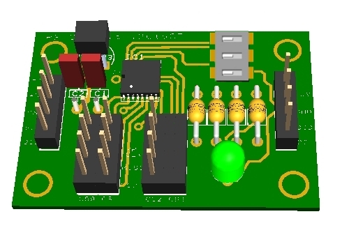
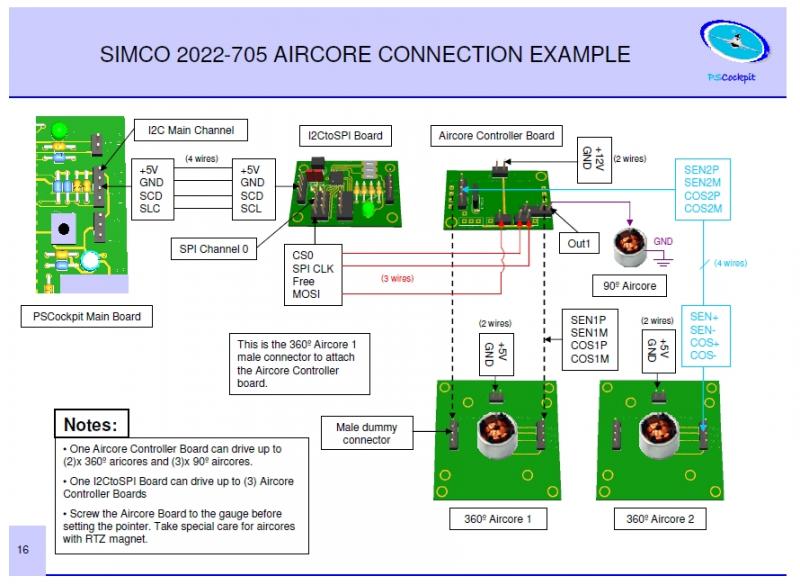
- I2CtoSPI pcb: This board is used to convert the I2C signal to SPI format. It must be connected to the I2C Main Channel of the PSCockpit Main Board to the Aircore Controller board:
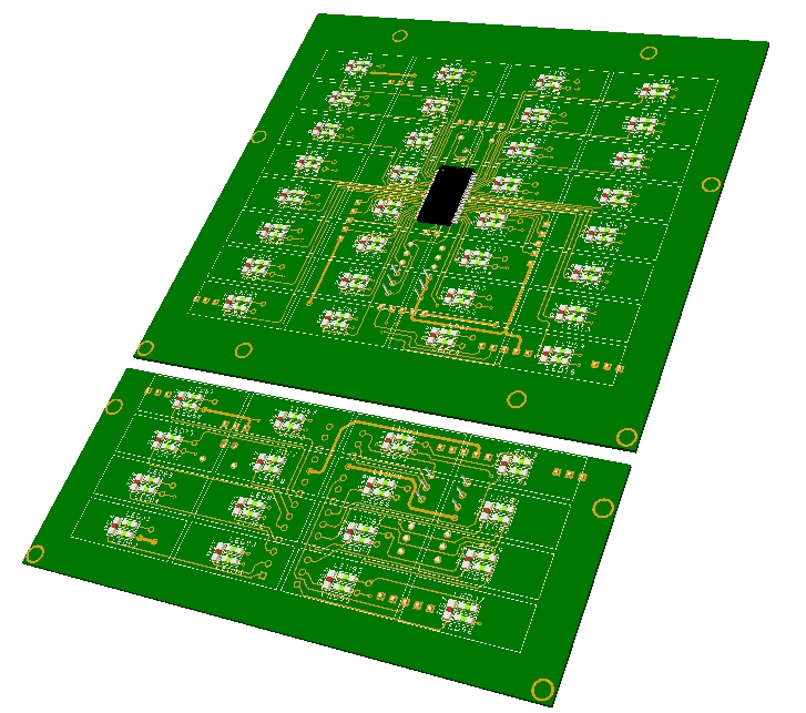
- Aircore Controller pcb: This board receives the SPI signal and drives (2) x 360º aircores plus (3) x 90º aircores. It must be connected to the I2CtoSPI board and to the Aircore pcb:
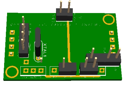
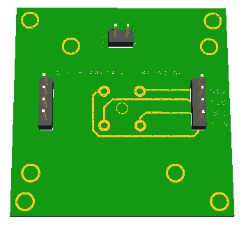
- Aircore pcb: This board supports the aircore and can be attached to your gauge. It must be connected to the Aircore Controller pcb:
The detail description of each board and the general overview of the system can be found in the PSCockpit System Quick Guide v2, which can be downloaded at
http://www.mediafire.com/view/o7k6hvkt0y671iq/QuickGuideV2.pdf
Step 1: Placing your aircore in the Aircore pcb
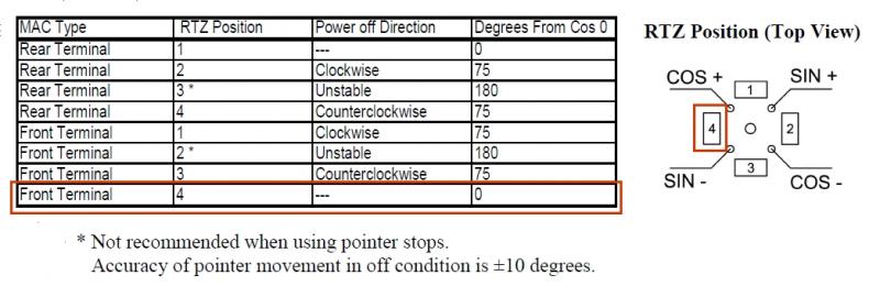
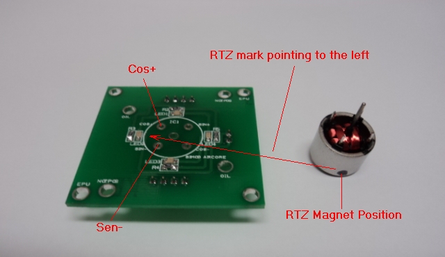
The supplied Simco 2022-705 aircores have terminals on the front and have a Return to Zero magnets (RTZ option). This option allows the aircore to return to zero position when power is deactivated. You must, then, find the correct position of the aircore motor in the aricore pcb in order to match the 0 physical position to the 0 electrical position, otherwise, once configured, the needle will point to other value of your gauge when power is off.
So, according to the Simco manual, the RTZ has to be located between cos+ and sen – terminals:
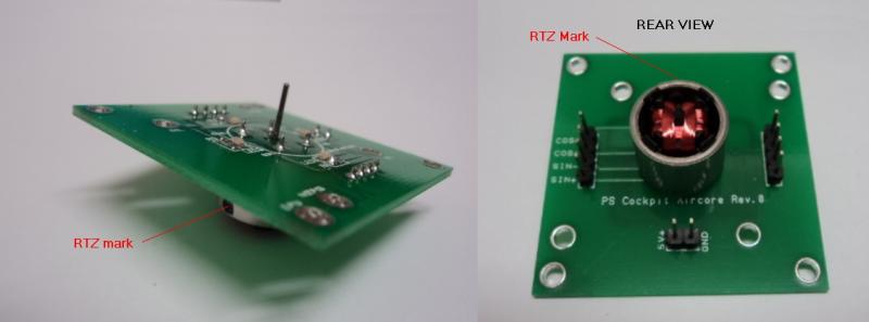
You will find a black mark on your aircore where the RTZ magnet is located:
And the final assembly:
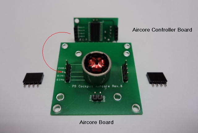
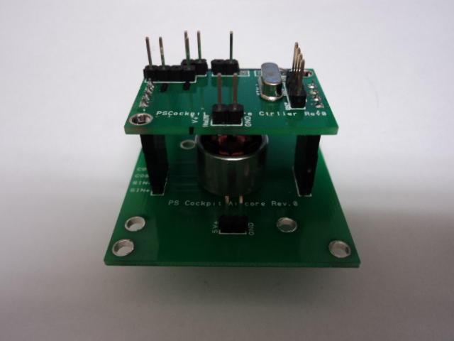
Step 2: Attaching the Aircore Controller Board to the Aircore Board:
As the aircore body height is larger than the connectors, you will need two additional connectors which will act like spacers. Look for the correct position of the Aircore Controller board:
Aircore Controller Board attached to the Aircore board:
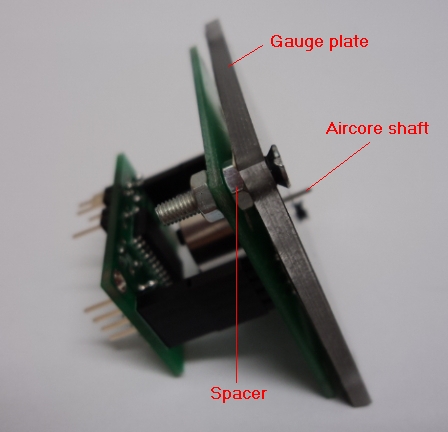
Step 3: Attaching the Aircore to your gauge
Use the holes of the Aircore board to fit it to your gauge plate. You will need some spacers to adjust the height of the aircore shaft:
You can also cut the board carefully if it exceeds your gauge plate.
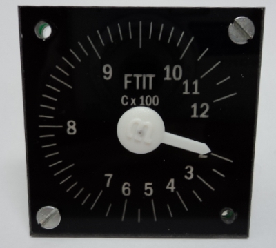
Now you can insert the pointing needle in to the aircore shaft pointing to the minimum value of your gauge scale:
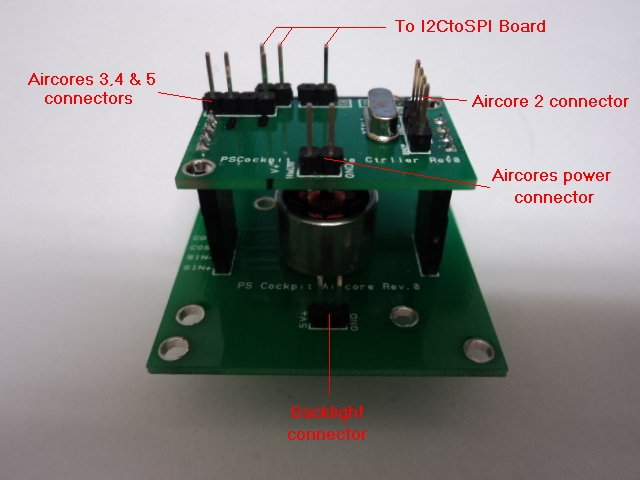
Step 4: Connecting the Aircore Controller Board
Refer to the PSCockpit Guide v2 for details connections. Basically:
You can supply power to the Aircores power connector from 5V to 12V. With higher voltage the aircore will move faster and it will have more par but I found that 5V is more than enough for a weightless needle.
Step 5: Testing the aircore
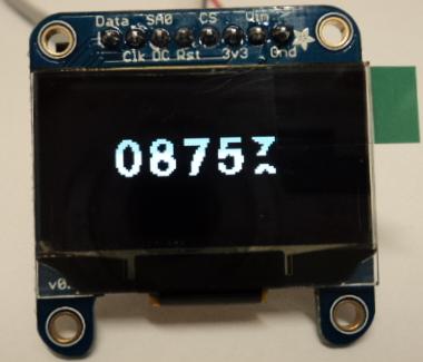
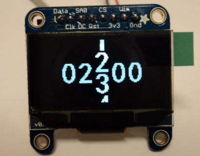
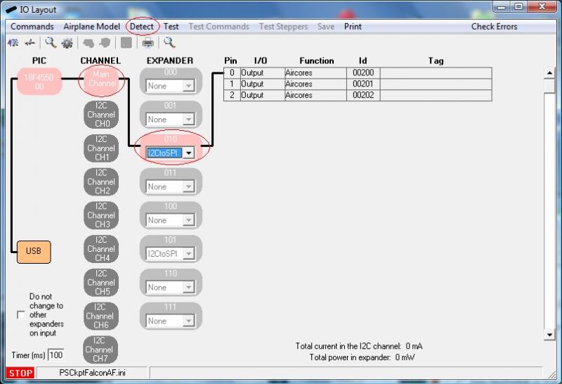
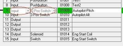
Go to IOLayout page of the PSCockpit Software and select I2CtoSPI in the Expander address according the one selected in your board:
As the I2CtoSPI board can drive 3 Aircore Controller boards, you will see these 3 channels with different Ids. First Id (00200 in the picture) is the CS0 channel of your Aircore Controller board, second Id is the CS1 channel and third Id is the CS2 channel. CS3 channel of the I2CtoSPI board is not used and must remain unconnected.
Click on “Detect” and you will see the Expander in pink if the expander has been detected.
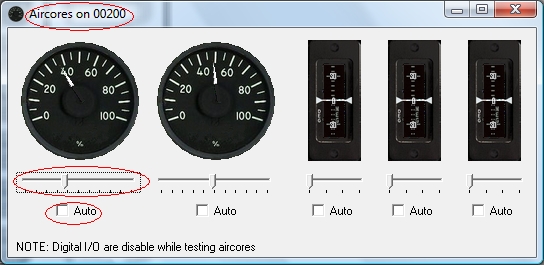
Click on “Test” and a “+” button will appear besides each of the Id channels. When you click on “+” button another screen will be opened showing the (2) x 360º and the (3) x 90º aircores connected to that channel. You can move any of the sliders and the aircore will move accordingly. You can also check the “Auto” check box to see the aircore moving continuously:
You can now power off your system and you will see the gauge needle returning to zero position.
Step 6: Configuring the Servos/PWM/Aircores
Since PSCockpit Software V 0.9.4 you can access directly to the Servos/PWM/Aircores configuration page. In this page you can configure the maximum/minimum scale of your gauge and the intermediate scales if your gauge has any.
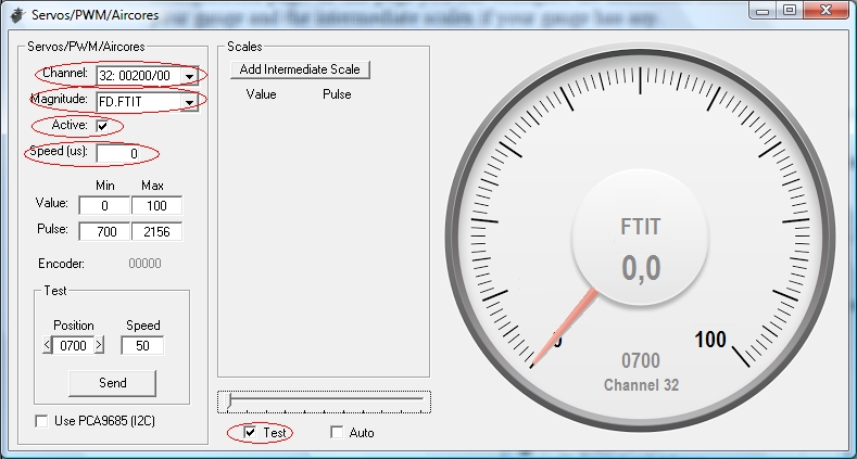
To configure a desired aircore select the following parameters:
1. Select the aircore from the “Channel” display list. For each Id (SPI channel) you will see aircores from 0 to 4.
2. Select the sim value you want to be displayed on your gauge in the “Magnitude” display list.
3. Check the “Active” checkbox to enable the gauge.
4. Select the desire “Speed” of your gauge. Using the SSC-32 board for servos, this value will determine the microseconds will take the servo to go from one position to another. For the rest of the systems, aircores and servos with the Adafruit board, it is used to limit the minimum change of the variable to be sent to the gauge.
If you check the “Test” checkbox you can use the slider to move the selected gauge.
The first thing to do now is to find the lower and upper positions of your gauge and look what the pulses are the ones that match those positions. Move the slider (with the “Test” checkbox marked) to move your gauge needle until the lower value of your gauge is reached. The slider can be moved precisely with the left and right arrows of your keyboard once the slider is selected with your mouse. You will note that the “Position” value of the “Test” frame will change its value. When the gauge needle is in its lower position, this value has to be put in the Min Pulse box. Also put the minimum value of the gauge in the Min Value box:
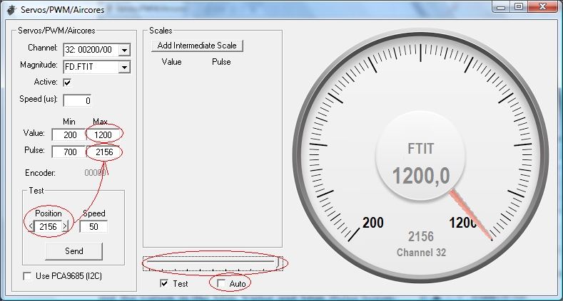
To find the upper position of the gauge repeat this procedure by moving the slider and put the values in the Max Value and Max Pulse boxes:
You can test your gauge by checking the “Auto” checkbox. You will see the gauge needle moving from the lower to upper positions without exceeding any of them. The “Speed” value of the Test frame is the amount added to the position, so you can reduce to a minimum of 10 to see your gauge moving smoothly.
Step 7: Adding intermediate scales to your gauge
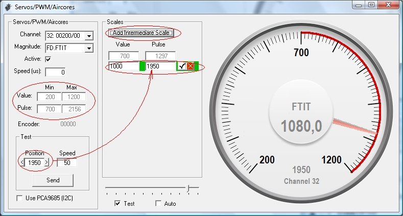
If your gauge has different scales, you can add them easily by clicking on the “Add Intermediate Scale” button. Two text boxes will appear where you have to put the value and the pulse that correspond to that intermediate scale. Repeat the above procedure by moving the slider until the gauge needle is pointing to the intermediate scale value.
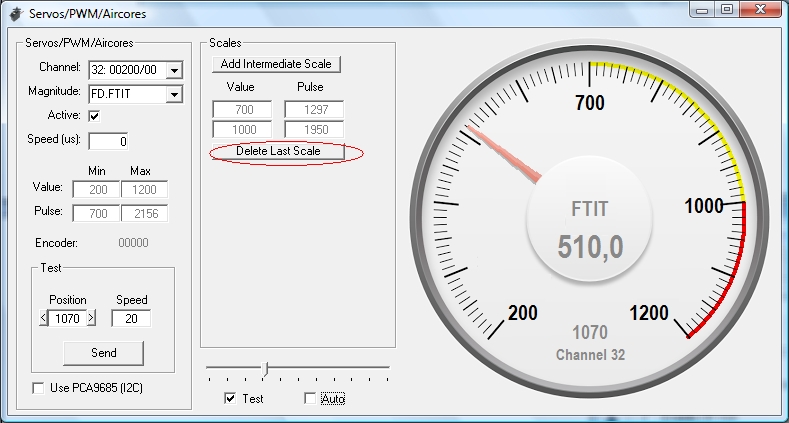
When any intermediate scale is added the minimum and maximum gauge values and pulses are disabled and can not be changed. To change these values you will have to remove the intermediate scales.
If you test your gauge now by selecting the “Auto” checkbox, you will see the gauge needle moving around the scales with different speeds.
Your aircore is now configured and you can use it with your favourite sim in Run mode of the PSCockpit Software.
One last consideration:
If you see your gauges moving a little jerky you can adjust them by setting the speed to 0 and resetting the timers on the “USB timers” page of the PSCockpit Software: try 10 ms for the “Sim data” timer and 0 for the “Between cycles” timer. Be aware that this will influence some other elements like encoders and/or 8x4 matrixes, so you will have to find the correct compromised values.
Regards,
Shep


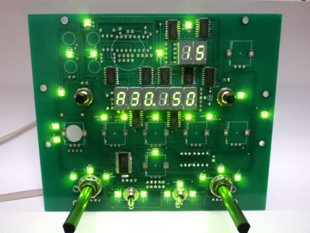
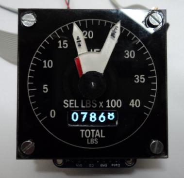
 .. this is what you will get...