Time to launch a new run of the PSCockpit System!!
New boards for this run:
- PWM board for backlights
- ELEC board
- AUDIO1 and AUDIO2 board
More info about above boards to follow.
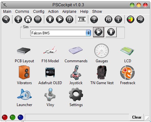
Version 1.0.3 of the PSCockpit software with vJoy implementation for analogue and DX buttons:
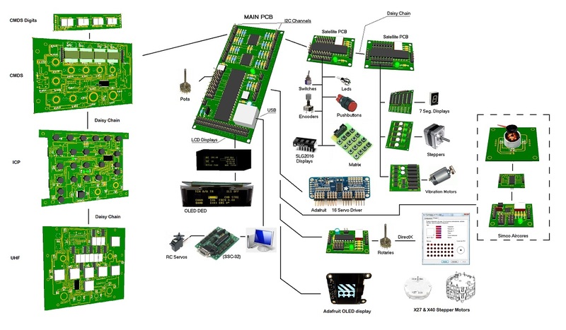
 System Description
- One stop hardware and software for cockpit systems. Once the cockpit is connected you can configure the software individually for each sim.
- Easy configuration and setup for people without electronic knowledge.
- Avoid excessive wiring runs along the cockpit.
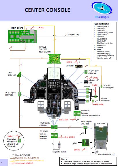
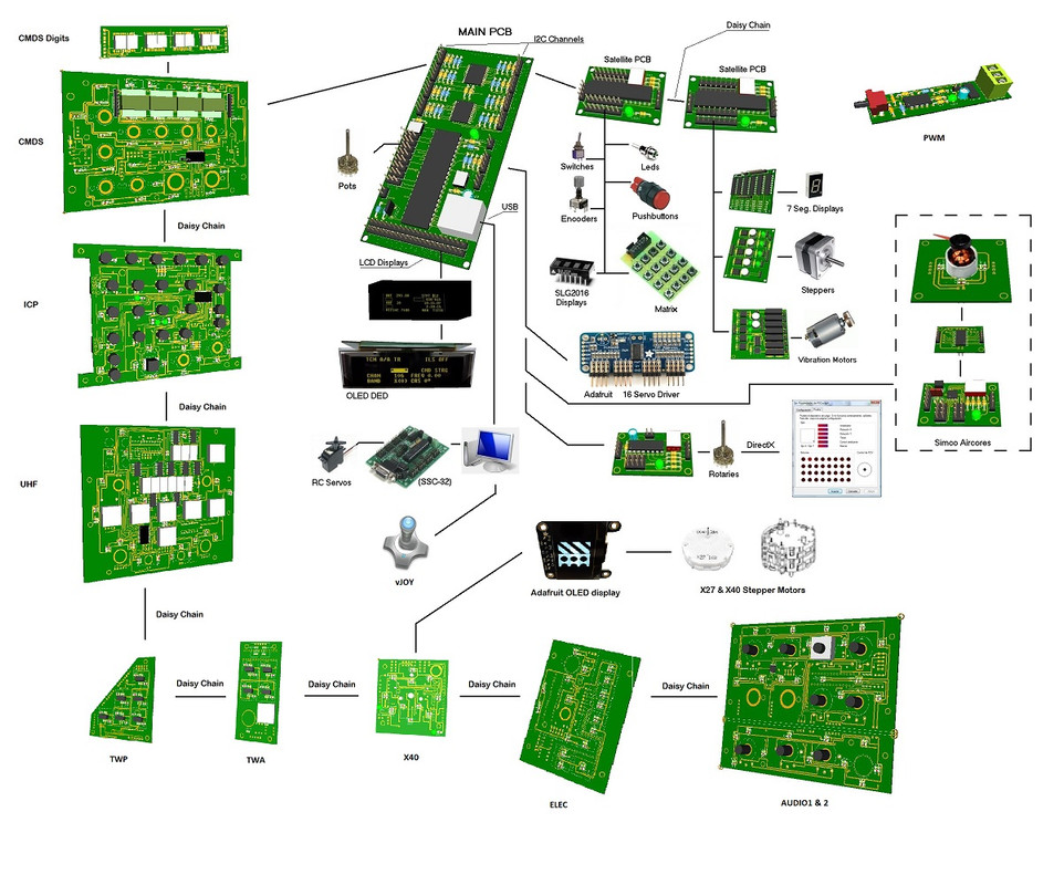
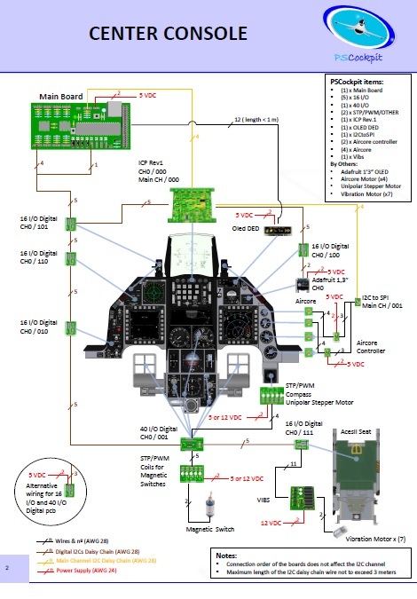
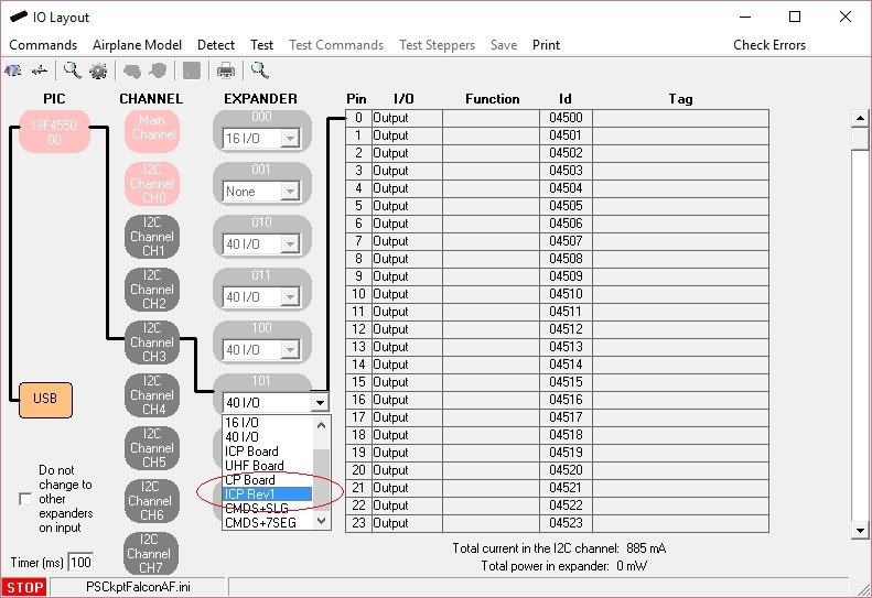
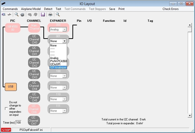
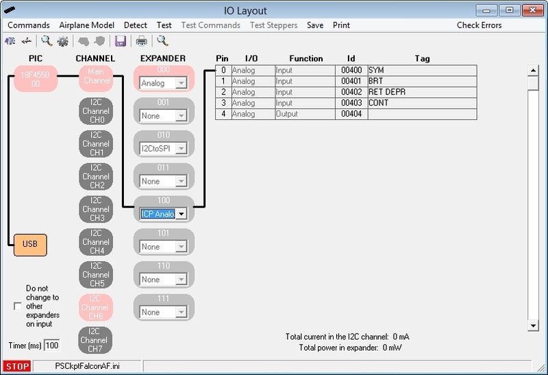
The system uses small satellite PCB’s that can be distributed along the cockpit. The communication between these satellite PCB’s and the Main PCB is done with only 2 wires (I2C protocol) plus the power cables. These wires can be connected in daisy chain. The idea is to wire each of the cockpit panels to only one satellite PCB. See F16 distribution example:
You can download at:
http://psfalcon.blogspot.com.es/2016/12/ps-cockpit-system-f16-distribution-file.html
Supported devices
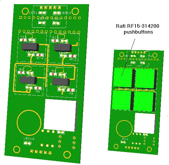
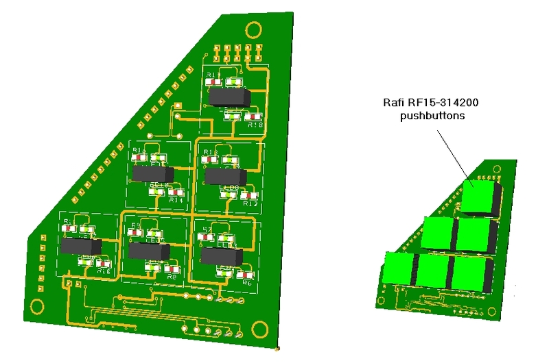
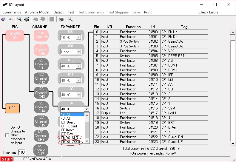
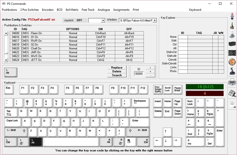
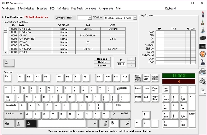
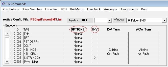
- Digital inputs: Pushbuttons, 2 position switches, 3 position switches, digital encoders, BCD encoding (8 to 3, 16 to 4, 32 to 5) and 8x4 matrixes
- Digital outputs and leds
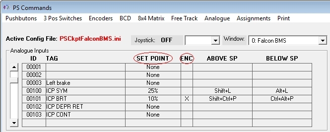
- Analogue inputs and outputs
- Vibration motors
- Aircores motors
- Stepper motors: Unipolar, X27 and X40
- RC Servomotors
- Segment Displays: 7 segments and SLG2016
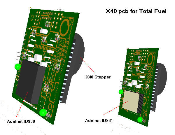
- LCD displays: SSD1322 Graphic display 264x64, KS0108 Graphic display 128 x 64, KS0108B Text display 20x4, SSD1306 Adafruit 128x64 (ID938 and ID931)
More information, downloads and guides at
http://psfalcon.blogspot.com.es/2015/05/pscockpit-system-up-to-date-software.html
Prices
The prices of the PCB’s already mounted and tested are the following:
- Main PCB: 60 €
- Digital expander for 40 inputs/outputs: 33 €
- Digital expander 16 inputs/outputs: 10 €
- Steppers/Other voltage outputs pcb: 28 €
- 7 segment displays pcb for 6 displays: 18 €
- Analogue pcb for 4 inputs/ 1 output: 20 €
- Yellow OLED display (85mm x 40mm), 256x64 for DED or PFL: 55 €
- I2CtoSPI pcb: 25€
- Aircore Controller pcb: 24€
- Aircore pcb: 15€
- Vibration motors pcb: 38€
- I/O Enhancement pcb: 6,5€
- Caution Panel board: 40€
- UHF board: 90€
- ICP pcb Rev 1: 90€
- CMDS board (with 2 rotary switches 30º & 45º, no toggles, no displays): 80€
- CMDS options:
- Miniature toggles 6 mm diam. (1 with locking lever): 40€
- SGL2016 displays: 35€ (each)
- HDLG-1414 displays: 20€ (each)
- 7 segment displays pcb with 8 displays: 35€
- TWP board: 40€
- TWA board: 20€
- X40 stepper board: 20€
NEW BOARDS:
- PWM board: 20€
- ELEC board: 50€
- AUDIO1 & AUDIO2 board: 100€
- Shipment: 15€ / 25€ depending on the total weight order
Time Line:
- Orders will be accepted until Dec. 17th.
-
Only direct bank transfers for payments. Sorry for the inconvenience.
- Delivery: Starting February 2017
Regards,
Shep


