If you are planning to use 7 segment displays to display the UFC and Aux Tacan Channel you have tree options in the PSCockpit system:
- Using (4) 7seg. displays.
- Using (3) 7 segment displays and (1) 14 segment alphanumeric display
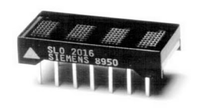
- Using 4-Digit 5x7 Dot Matrix Alphanumeric Intelligent Display SLG2016
And the last option, only for the Aux Comm Tacan Channel, using the Cherry pushwheels.
Option 1: Using (4) 7seg. displays.
Configure your 7s displays as usual in the IO Layout:
Select the correct Id in the F16Model page by clicking on 7S Display and make the configuration of your 4 digits as shown in the picture:
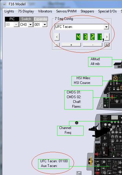
Now, when you run your sim ,the PSCockpit software will display the Tacan channel in the first 3 digits of the display and the last one will show a 0 when the band X is selected in the sim and will show a 1 when the band Y is selected in the sim.
Option 2: Using (3) 7 segment displays and (1) 14 segment alphanumeric display
To use this option you must try to get 14 segment displays with the same dimensions that the 7 segment displays, the same colour and the same brightness. This could be difficult to find.
Remember that all segment display have to be Common Cathode as well as the 14 segment display.
I have found the Kingbright PSC39-21GWA is a little bigger that the Avago HSDP-7803 and probably can be use it. But, sorry, I didn’t try it.
As before, configure your 7s displays as usual in the IO Layout, this time using a 3x7 Seg. Display.
Now we have to connect the segments. We are going to use to a 5VDC power supply. To limit the current to 25 mA we will use a 120 Ohms resistor. This resistor can be change a little 80-160 Ohms to get the same brightness as the rest of the 7 seg. displays. The wiring will be the following:
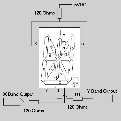
The resistor R1 might need also some adjustment to get the same brightness as the others.
Now, if we activate the X band output, will see an X on the display and if we activate the Y band output, will see and Y on the display.
The X and Y band outputs can be selected on the PSCockpit Software in the F16 Model page (Lights) as shown in the picture:
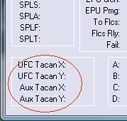
Option 3: Using 4-Digit 5x7 Dot Matrix Alphanumeric Intelligent Display SLG2016
Proceed as a normal 4-Digit 5x7 Dot Matrix Alphanumeric Intelligent Display SLG2016 like explained in the following post:
http://psfalcon.blogspot.com.es/2012/08/how-to-use-5x7-dot-matrix-alphanumeric.html
Option 4: Using Cherry pushwheels.
The Cherry pushwheels are selector switches with very small dimensions for front-mounting. The ones we are going to use are the PE series with 10 switching positions BCD.

I have selected the Cherry PE C - A - 3 - 4 - 00 (4 digits BCD complete with end caps) and 3 spacers 609-0760 which gives me a total dimensions of 24x45 mm.
You may want to order also (2) stops 609-0013 to limit the first and last digit of your auxiliary tacan channel. Look at the Cherry catalogue for other options as illumination.
To set the Cherry pushwheel for realism you will have to dismantled under your responsibility the first digit to change the number strip to 0-1-0-1-01-…. and X-Y-X-Y-… for the last digit.
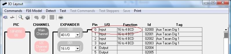
To connect each of the pushwheel to the PSCockpit System, go to I/O Layout page and select “16 to 4 BCD” inputs in a location with 4 consecutive inputs free:
We have to wire each of the pushwheel as shown in the picture according to the pins selected in the IO Layout page:
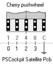
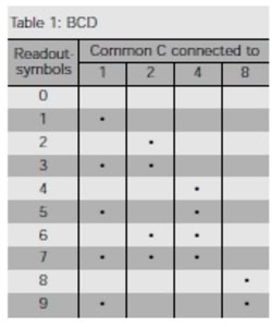
To test the Cherry pushwheel click on test and verify that the inputs are ON according to the following true table:
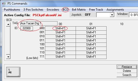
Once we have tested each of the pushwheels we have to put the commands to be sent to the sim. For this, go to the Commands page, select BCD, select the correct ID for each pushwheel and fill the matrix with the command that changes the Aux Tacan channel in your sim, in this case, for digit number one, Shift+F1.
If you want to get your Aux Tacan channel in synchrony with the sim, go to F16 Model page, select Special I/Os, fill the data of the Aux Tacan channel and check the checkbox “Aux Tacan Synchro”:
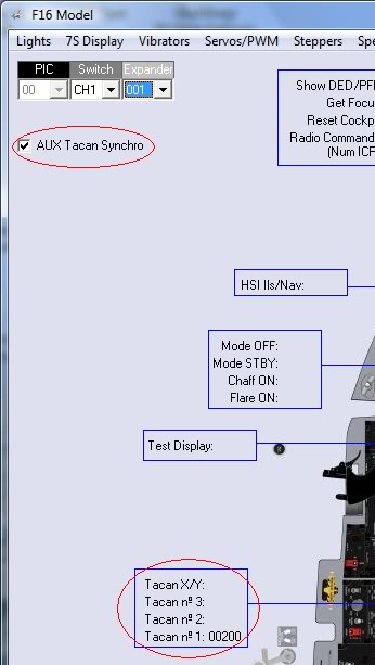
Now, when you enter the cockpit the tacan channel of the sim will display your cockpit tacan channel. Yihaaaaaa.
Regards,
Shep
Wednesday, August 29, 2012
Friday, August 24, 2012
HOW TO use 5x7 Dot Matrix Alphanumeric Intelligent Display SLG2016
The SLG2016 is a four digit 5x7 dot matrix display module. The integrated circuit contains memory, a 128 ASCII ROM decoder, multiplexing circuitry and drivers. The character set consists of 128 special ASCII characters.
Display interconnection is very straightforward, look for the spec sheet.
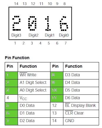
In the PSCockpit System you have to connect 10 outputs from the 16 or 40 I/O boards directly to the diplay inputs as shown in the figure in green. All other pins have to be connected as per its specification sheet.
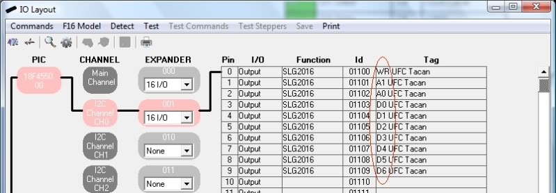
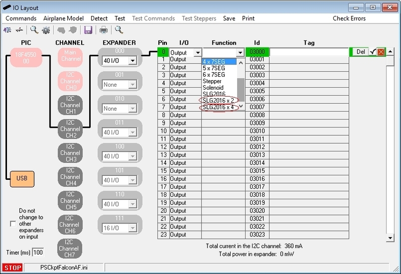
To select this type of display in the PSCockpit system, go to IO Layout page and select the SLG2016 from the Function dropdown list. The chosen output must have nine more free outputs. Once accepted, you will see which output has been assigned to do the correct wiring:
Edited on April 11th, 2016
------------------------------------------------------------------------------------------------------------------------
It is possible to group (2) or (4) SLG2016 displays in a row with adding just one wire more for each display.
You can select this grouping from the dropdown list:
------------------------------------------------------------------------------------------------------------------------
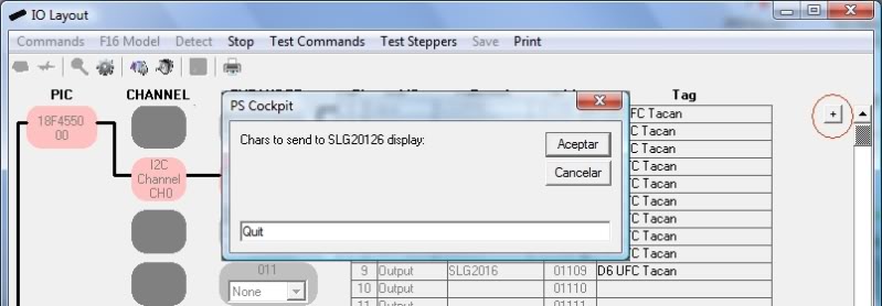
To test the display, once in Test Mode, click on the “+” symbol and you will be prompted to enter the desire text to be displayed. Once you accept, the display will show the text.
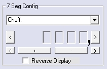
To configure the display to run from your favourite sim, go to F16 Model page and proceed as a normal 7 Segment display like explained in the following post:
How to 7-segment displays
Edited on April 11th, 2016
-------------------------------------------------------------------------------------------------------------------------
For the SLG2016 the above formatting should be 4 digits:
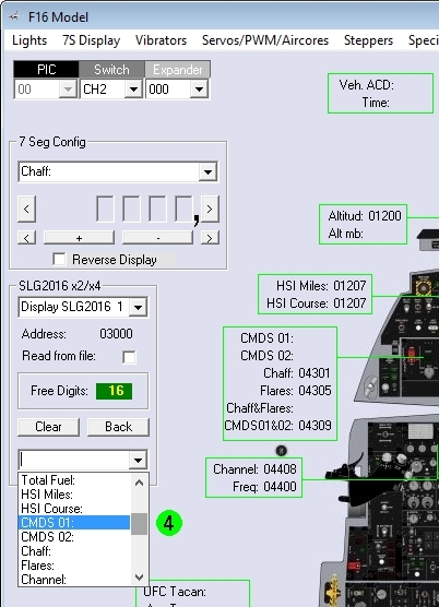
Once you have defined the length of the values you are going to use in the SLG2016 displays, if you use the SLG2016 grouping options (x2) or (x4), you have to group also the values of the sim you will be sending to the displays.
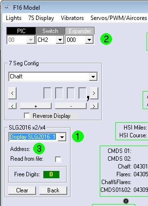
This grouping configuration is made in the 7 Segment Displays menu of the Airplane Model page of the PSCockpit Software doing the following procedure:
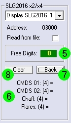
1. Select the SLG2016 slot to save the configuration with the dropdown list. There are a maximum of 10 slots.
2. Select the expander address where the SLG2016 are connected
3. Click on Address and select the SLG2016 group. The first pin address will appear besides the Address label, the free digits will be updated and a drop down list will appear at the end of the frame.
4. Select the first magnitude that will appear in the left most digits of the SLG2016 group. Once selected the magnitud the dropdown list will change to orange where you can select one of the operations available to change the magnitude value (=, *10, *100,....,/10, /100,...).
6. At the end of the frame you will see the list of the magnitudes of the group with the digits in brackets and the operation that will be made to each of the magnitudes.
7. You can use the Back command to delete the last magnitude from the list.
8. You can use the Clear command to delete all the list.
Regards,
Shep
Saturday, June 9, 2012
PSCockpit Quick Guide
It will help you on wiring the system in your cockpits.
Download from: http://www.mediafire.com/view/?6kacpd31w3bvvve
Regards,
Shep
Monday, April 23, 2012
PS Gauges Update
Hi everyone,
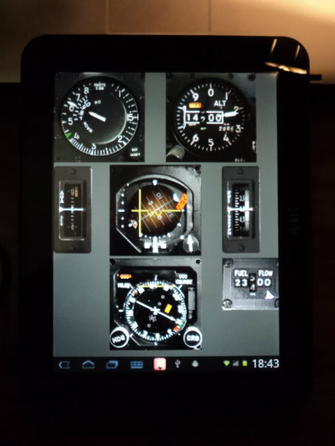
Got my Airis OnePad 970 yesterday!!!
Here is a picture with the center console gauges with PSUdp software:
I made a little update on PSGauges to fix a display problem regarding the different dip of the device.
You can download it here: Update
Regards,
Shep
Got my Airis OnePad 970 yesterday!!!

Here is a picture with the center console gauges with PSUdp software:
I made a little update on PSGauges to fix a display problem regarding the different dip of the device.
You can download it here: Update
Regards,
Shep
Sunday, April 22, 2012
PS Cockpit Software
You can download the PSCockpit v.0.8.0 (Beta) sofware to control the PSCockpit System in the following link: http://www.mediafire.com/download.php?d80terg9airfhd2
Use it at your own risk!!!
Regards,
Shep
Use it at your own risk!!!
Regards,
Shep
Monday, January 16, 2012
HOW to Make Your Own Configuration with the PSCockpit System
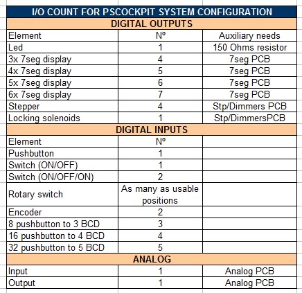
The list of the number of outputs/inputs you need per element is the following:
For digital inputs/outputs you can select two types of expanders: 16 I/O and 40 I/O. You can mix inputs and outputs in each expander as they are configurable but there are several restrictions to take in account:
a) The elements can’t share expanders: For example, if you are planning to use a 32 pushbutton inputs matrix you need a expander with (5) inputs unused, you can’t use (3) inputs of one expander and (2) inputs of other expander.
b) Maximum current per I/O: 25 mA for the 16I/O, 15 mA for the 40 I/O.
c) Maximum power dissipation per expander: It means you can’t use all the expander for outputs to handle 25 mA because it should exceed the power dissipation capacity of the expander. As it depends on the ambient temperature and the heat dissipation method, I will establish some limiting values by testing the expanders.
d) The daisy chain for the expanders connected to one channel should not exceed 1A current, but if you need more, you can disconnect the daisy chain power supply at one point and supply power in it.
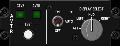
Example: AVTR panel
The panel consists of the following elements:
- (2) leds => 2 outputs
- (1) pushbutton => 1 input
- (1) 3pos switch => 2 inputs
- (1) rotary switch with 4 positions => 4 inputs
Total I/O count: 9 I/O. Expander selected: 16 I/O
That was easy. As I have 7 I/O free in this expander and I want to save some money, I will be using the expander to add another near panel in it. I found it!!:
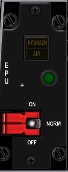
EPU panel
The panel consists of the following elements:
- (3) leds => 3 outputs
- (1) 3pos switch => 2 inputs
Total I/O count: 5 I/O to add to the above expander.
This is how I calculated the list of expanders you can find attached in the following post:
http://www.viperpits.org/smf/index.php?topic=7237.msg98798#msg98798
Things get a little more complicated once you have calculated all the expanders and you have to group them in rows of 8 to connect them to one I2C channel. But I’m sure nothing you guys can't resolve .
Regards,
Shep
For digital inputs/outputs you can select two types of expanders: 16 I/O and 40 I/O. You can mix inputs and outputs in each expander as they are configurable but there are several restrictions to take in account:
a) The elements can’t share expanders: For example, if you are planning to use a 32 pushbutton inputs matrix you need a expander with (5) inputs unused, you can’t use (3) inputs of one expander and (2) inputs of other expander.
b) Maximum current per I/O: 25 mA for the 16I/O, 15 mA for the 40 I/O.
c) Maximum power dissipation per expander: It means you can’t use all the expander for outputs to handle 25 mA because it should exceed the power dissipation capacity of the expander. As it depends on the ambient temperature and the heat dissipation method, I will establish some limiting values by testing the expanders.
d) The daisy chain for the expanders connected to one channel should not exceed 1A current, but if you need more, you can disconnect the daisy chain power supply at one point and supply power in it.
Example: AVTR panel
The panel consists of the following elements:
- (2) leds => 2 outputs
- (1) pushbutton => 1 input
- (1) 3pos switch => 2 inputs
- (1) rotary switch with 4 positions => 4 inputs
Total I/O count: 9 I/O. Expander selected: 16 I/O
That was easy. As I have 7 I/O free in this expander and I want to save some money, I will be using the expander to add another near panel in it. I found it!!:
EPU panel
The panel consists of the following elements:
- (3) leds => 3 outputs
- (1) 3pos switch => 2 inputs
Total I/O count: 5 I/O to add to the above expander.
This is how I calculated the list of expanders you can find attached in the following post:
http://www.viperpits.org/smf/index.php?topic=7237.msg98798#msg98798
Things get a little more complicated once you have calculated all the expanders and you have to group them in rows of 8 to connect them to one I2C channel. But I’m sure nothing you guys can't resolve .
Regards,
Shep
Wednesday, January 11, 2012
HOW TO use analog inputs with the PS Cockpit System (PSJoystick)
The PSJoystick allows the PSCockpit system to read analog inputs from an analog expander and send them to the PC as joystick axes so they can be configured in your favourite sim as a direct input.
Edited on Aug, 17th, 2022:
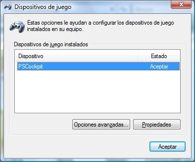
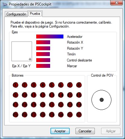
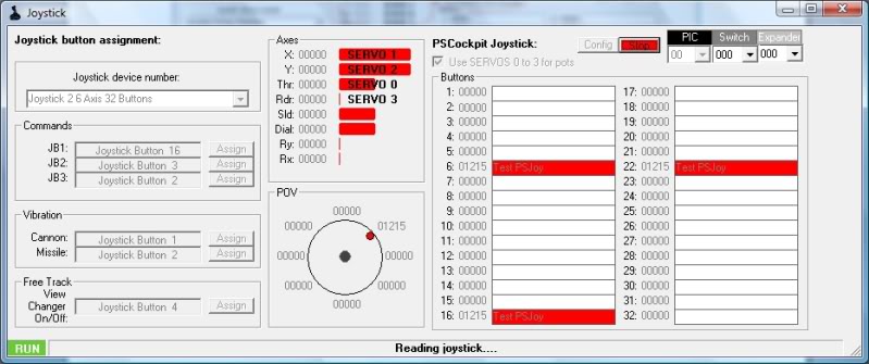
Once the PSCockpit Main Board is connected to the PC it will be detected by the system as a joystick with 32 buttons, 8 axes and 1 POV hat. To verify everything is correct go to Game Devices and you will see a device named PSCockpit:
Opps, it is in Spanish!!. Sorry for that.
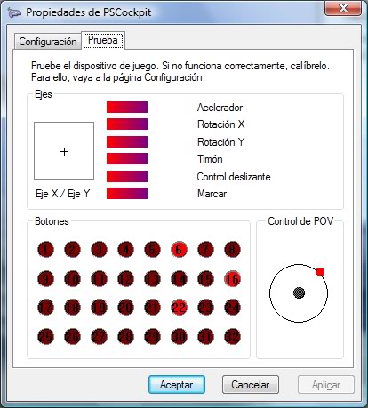
Click on Properties to see the device:
Opps, in Spanish again!! 
Configuring the joystick
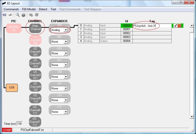
To configure the system we have to add an analog expander. Open the IO Layout page of the PSCockpit software and select Analog on the expander dropdown list. You will see the list of analog inputs and outputs available for the Analog expander. In the tag section you can put the name of the device:
Note: Analog expander can only be used on the Main Channel.
You can add up to 8 analog expanders to the system but as we have only 8 axes it should be enough to attach only two. We will find another good use for the rest of analog expanders…
Let’s now configure the analog inputs, buttons and the POV of the PSJoystick.
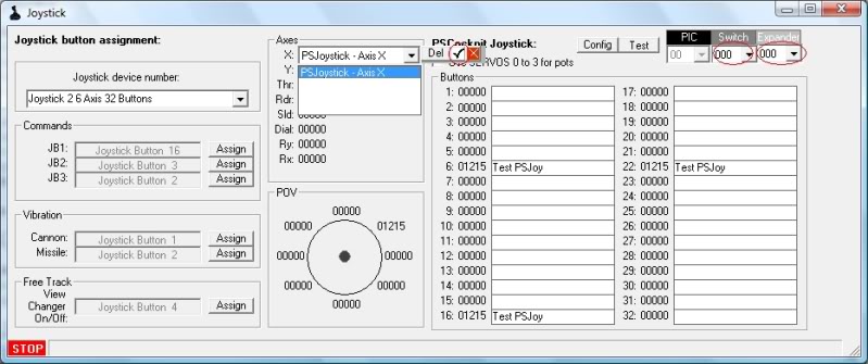
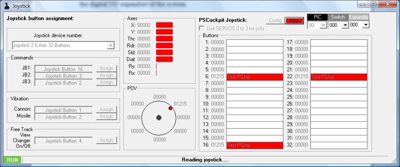
Open the Joystick page of the PSCockpit system and configure what axis you want to drive with the analog input by selecting the switch and the expander and clicking on the ID to see a dropdown list with the analog input tags we have entered before:
You can assign also the joystick buttons and POV buttons selecting the desire inputs of the digital I/O expanders of the system.
Once everything is configured, click on the “Config” command to send the values to the PSCockpit Main Board. The configuration values will be stored in the eeprom of the pic and they will be used even if you don’t run the PSCockpit software. Be careful to not detach the Main Board while writing the configuration.
Time to test!!!
Click on the “Test” command and you will see the PSJoystick working:
You can also see it working on Game Devices of Windows:
Opps. Spanish again!!
What if I don’t have yet the analog expander?
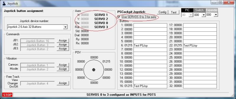
For the people not using the servos 0 to 3 outputs of the Main Board, you can use them as inputs for pots. In this situation, click on the check box “Use SERVOS 0-3 for pots” and the Main Board will read the pots values on these inputs:
Click again the “Config” command and after writing the eeprom, click on the “Test” command:
Regards,
Shep
========================================================================
If you have more than 2 analogue expanders on your PSCockpit system or your PSJoy driver is not working, you can use vJoy software.
See this post for more information: How to Use Vjoy
========================================================================
Once the PSCockpit Main Board is connected to the PC it will be detected by the system as a joystick with 32 buttons, 8 axes and 1 POV hat. To verify everything is correct go to Game Devices and you will see a device named PSCockpit:
Opps, it is in Spanish!!. Sorry for that.

Click on Properties to see the device:

Configuring the joystick
To configure the system we have to add an analog expander. Open the IO Layout page of the PSCockpit software and select Analog on the expander dropdown list. You will see the list of analog inputs and outputs available for the Analog expander. In the tag section you can put the name of the device:
Note: Analog expander can only be used on the Main Channel.
You can add up to 8 analog expanders to the system but as we have only 8 axes it should be enough to attach only two. We will find another good use for the rest of analog expanders…

Let’s now configure the analog inputs, buttons and the POV of the PSJoystick.
Open the Joystick page of the PSCockpit system and configure what axis you want to drive with the analog input by selecting the switch and the expander and clicking on the ID to see a dropdown list with the analog input tags we have entered before:
You can assign also the joystick buttons and POV buttons selecting the desire inputs of the digital I/O expanders of the system.
Once everything is configured, click on the “Config” command to send the values to the PSCockpit Main Board. The configuration values will be stored in the eeprom of the pic and they will be used even if you don’t run the PSCockpit software. Be careful to not detach the Main Board while writing the configuration.
Time to test!!!
Click on the “Test” command and you will see the PSJoystick working:
You can also see it working on Game Devices of Windows:
Opps. Spanish again!!

What if I don’t have yet the analog expander?
For the people not using the servos 0 to 3 outputs of the Main Board, you can use them as inputs for pots. In this situation, click on the check box “Use SERVOS 0-3 for pots” and the Main Board will read the pots values on these inputs:
Click again the “Config” command and after writing the eeprom, click on the “Test” command:
Regards,
Shep
Wednesday, December 7, 2011
HOW TO Encoding/Multiplexing with the PS Cockpit System
When you have a certain amount of pushbuttons in a system where only one of them is going to be pressed at a time (i.e. keyboard) there is an electrical interface technique to reduce the number of total inputs called multiplexing or encoding.
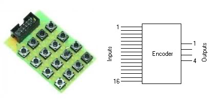
The device used for multiplexing is known as a multiplexer or encoder. You can find this type of chips in the electronic market. Pitifully, these chips encoders can handle only a maximum of 16 inputs to encode 4 outputs as, for our purposes, we should need a 36 inputs/5 outputs encoder to use it for ICP and MFDs keyboards.
PS Cockpit System can handle 3 types of encoders:
- 8 inputs to 3 outputs.
- 16 inputs to 4 outputs.
- 32 inputs to 5 outputs.
For the first two you can always use an encoder chip or make it of your own as we are going to do here for a MFD.
Making the truth table
The first thing to do is to make the truth table for the MFD. This is where the relationship between the given pushbuttons and the outputs is going to be established.
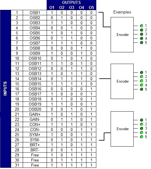
We have 28 pushbuttons in a MFD, 20 OSB plus 8 for GAIN, CON, SYM and BRT. The truth table will be:
You can see in the examples that each pushbutton will activate the corresponding outputs of the encoder.
Electrical schema
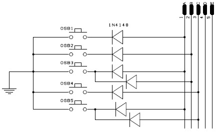
To translate the truth table to an electrical schema we have to just set the 5 outputs and the pushbuttons and make the wiring from the pushbutton to the output. In the examples, the OSB1 has to be connected only to output 1; the OSB14 has to be connected to output 2, 3 and 4; and the SYM- has to be connected to output 2, 3, 4 and 5.
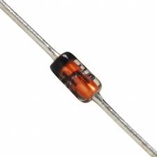
To isolate one pushbutton to another we will use the diode 1N4148, who is very useful at high frequencies with a reverse recovery time of no more than 4ns and very cheap, as we will need one of it per connection.
This is how the electrical schema looks like for the 5 first pushbuttons:
The complete schema in the PFD attached.
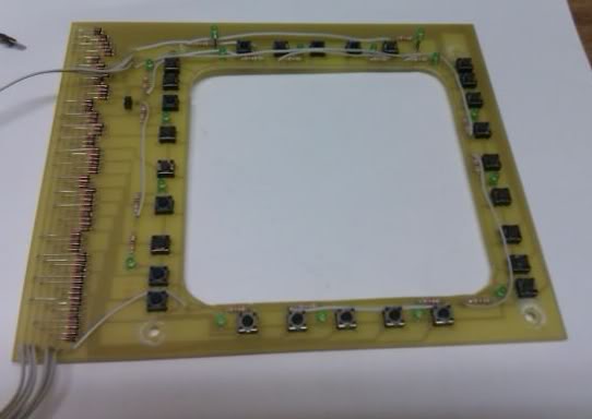
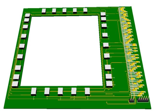
Now you can make the board with your favourite program:
And, of course, call your friend to make the board
.
Here you have the results of the MFD where I have added also some leds for lighting. Is anything more interesting than a few hours working on your favourite hobby?
Now we can connect the board to one of our expanders. I have chosen the 16I/O expander with 010 address and I have connected the MFD to pins 8 to 12.
PS Cockpit Software configuration
Now we are ready to tell the software were we have connected our MFD with a encoder system of 32 inputs to 5 outputs.
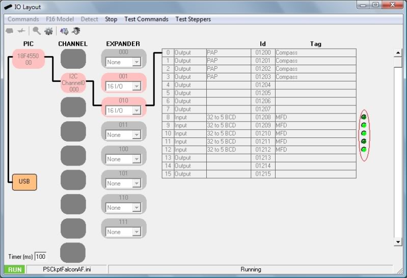
Go to the IO Layout page of the PS Cockpit Software, select I2C channel 0 and expander 010. In the corresponding pin 8 select “Input” from the dropdown list and 32 to 5 BCD of the function dropdown list. Set the desire TAG and accept.

Time for testing: Click on the “Test” command and you will see which inputs are activated when you press any of the pushbuttons:
Sending commands to the simulator
We have now to tell the PS Cockpit Software the commands we want to send the simulator on every key. Remember the truth table; each key will activate one or several inputs.
Open the Commands page and select BCD. With the scroll bar on the left you can select the corresponding tag. Depending on the type of encoder you will see a different table according with the amount of inputs. In this case, select the tag MFD and we will see a table of 32 cells where the columns are the first two outputs of the encoder (truth table = O1-O2 = low bits) and the rows are the last three outputs of the encoder (truth table = O3-O4-O5 = high bits).
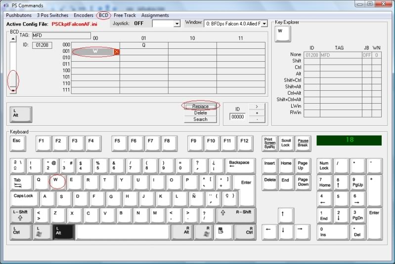
Select the corresponding cell and type the key to send to the simulator on the keyboard. Click on “Replace” command to accept:
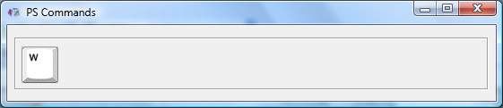
Time for testing: Go back to IO Layout page, click on “Test” command and on “Test commands”. A small window will appear and the corresponding command will be shown as you press any pushbutton:
Of course, you can always use (2) encoders of 16 inputs/4 outputs or use the 40I/O expander board of the PS Cockpit System to connect directly all the pushbuttons of the MFD.
Regards,
Shep
The device used for multiplexing is known as a multiplexer or encoder. You can find this type of chips in the electronic market. Pitifully, these chips encoders can handle only a maximum of 16 inputs to encode 4 outputs as, for our purposes, we should need a 36 inputs/5 outputs encoder to use it for ICP and MFDs keyboards.
PS Cockpit System can handle 3 types of encoders:
- 8 inputs to 3 outputs.
- 16 inputs to 4 outputs.
- 32 inputs to 5 outputs.
For the first two you can always use an encoder chip or make it of your own as we are going to do here for a MFD.
Making the truth table
The first thing to do is to make the truth table for the MFD. This is where the relationship between the given pushbuttons and the outputs is going to be established.
We have 28 pushbuttons in a MFD, 20 OSB plus 8 for GAIN, CON, SYM and BRT. The truth table will be:
You can see in the examples that each pushbutton will activate the corresponding outputs of the encoder.
Electrical schema
To translate the truth table to an electrical schema we have to just set the 5 outputs and the pushbuttons and make the wiring from the pushbutton to the output. In the examples, the OSB1 has to be connected only to output 1; the OSB14 has to be connected to output 2, 3 and 4; and the SYM- has to be connected to output 2, 3, 4 and 5.
To isolate one pushbutton to another we will use the diode 1N4148, who is very useful at high frequencies with a reverse recovery time of no more than 4ns and very cheap, as we will need one of it per connection.
This is how the electrical schema looks like for the 5 first pushbuttons:
The complete schema in the PFD attached.
Now you can make the board with your favourite program:
. Here you have the results of the MFD where I have added also some leds for lighting. Is anything more interesting than a few hours working on your favourite hobby?
Now we can connect the board to one of our expanders. I have chosen the 16I/O expander with 010 address and I have connected the MFD to pins 8 to 12.
PS Cockpit Software configuration
Now we are ready to tell the software were we have connected our MFD with a encoder system of 32 inputs to 5 outputs.
Go to the IO Layout page of the PS Cockpit Software, select I2C channel 0 and expander 010. In the corresponding pin 8 select “Input” from the dropdown list and 32 to 5 BCD of the function dropdown list. Set the desire TAG and accept.

Time for testing: Click on the “Test” command and you will see which inputs are activated when you press any of the pushbuttons:
Sending commands to the simulator
We have now to tell the PS Cockpit Software the commands we want to send the simulator on every key. Remember the truth table; each key will activate one or several inputs.
Open the Commands page and select BCD. With the scroll bar on the left you can select the corresponding tag. Depending on the type of encoder you will see a different table according with the amount of inputs. In this case, select the tag MFD and we will see a table of 32 cells where the columns are the first two outputs of the encoder (truth table = O1-O2 = low bits) and the rows are the last three outputs of the encoder (truth table = O3-O4-O5 = high bits).
Select the corresponding cell and type the key to send to the simulator on the keyboard. Click on “Replace” command to accept:
Time for testing: Go back to IO Layout page, click on “Test” command and on “Test commands”. A small window will appear and the corresponding command will be shown as you press any pushbutton:
Of course, you can always use (2) encoders of 16 inputs/4 outputs or use the 40I/O expander board of the PS Cockpit System to connect directly all the pushbuttons of the MFD.
Regards,
Shep
Subscribe to:
Posts (Atom)