Friday, October 25, 2013

HOW to VIBRATORS/BASS SHAKERS

The PSCockpit Software is able to drive up to 6 vibration motors with 4 different speeds and/or send .wav files to your bass shaker within your favourite sim.

Vibration motors

The vibration motors are driven by means of 6 on/off signals and 4 speed signals. With this configuration you can use the vibration motor pcb.

To configure the vibration motors in the PSCockpit Software go to IOLayout and select Leds as ouputs. You will have to define the following outputs:
- (4) for speed signals
- (1) for general ON signal
- (x) for the individual ON/OFF motor signals
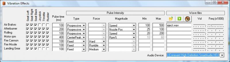


You can test your outputs, as usual, by clicking on “Test” command and activating the proper checkbox.

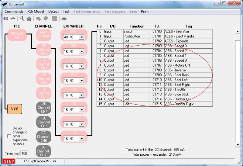
Now that we have defined the outputs, we have to tell the PSCockpit Software the function of each output. This is done in the “F16 Model” page, under the tab “Vibrators”. Just select in each position the correct Id of the output previously introduced:


The next step is to select the behaviour of the vibrator motors depending on the variables of the sim. To do this go to “Vibs Effects” from this page or from the Main Page of the PSCockpit Software. The following screen will be opened:
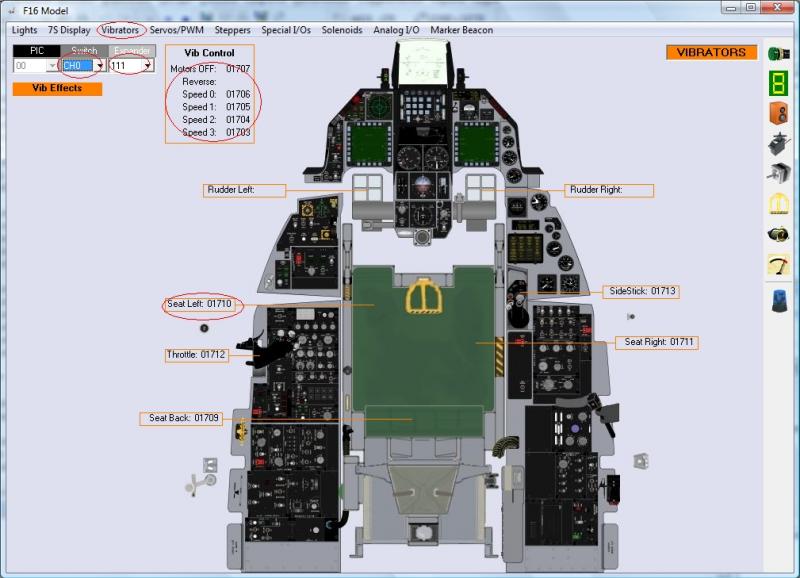


The actual variables of the sim that can be programmed are the following:
- Air brakes: becomes active when the airbrakes are deployed
- Afterburner: becomes active when the afterburner is reached
- Rolling: becomes active when you are on the ground
- Motor rpm: self explanatory.
- Fire Cannon: becomes active when you push fire cannon button of your joystick.
- Fire Missile: becomes active when you push fire missile button of your joystick.
- Landing Gear: becomes active while the landing gear is in extension/retraction movement.

Select in each checkbox what motors you would like to activate when a sim variable becomes active.

To define the pulse intensity you can define the following variables:
Type:
- Fixed: The pulse intensity is always the same.
- Progressive: The pulse intensity begins from Min. to Max. defined later
- Center peak: The pulse reaches the highest intensity in the middle of Min. and Max.

Force. If you have selected a fixed type, you can establish the force level:
- Off: No motor will be activated
- Slight: Speed 0 will be activated.
- Rumble: Speed 1 will be activated.
- Medium: Speed 2 will be activated.
- Hard: Speed 3 will be activated.

Magnitude: If you have selected a Center Peak or Progressive type, you can select one of the following sim varables:
- RMP%
- Speed
- RMPxSpeed
- Nozzle Pos
- Fuel Flow

Min. and Max: The values of these variables should match the selected magnitude variable and also will define the interval when the motors will be active.

Depending on all the above values the software will determine what motor speed output will be activated.

To assign the joystick buttons for cannon and missile fire go to “Joystick” page and assign the desire buttons:


Two examples:

- I would like to feel the runaway while taking off or landing, so I have selected the Rolling variable to activate all the vibrators in a progressive manner, depending on the speed from 20 to 200 knots. In this way as the speed on the runaways increases the vibration increase and will stop when the speed reaches 200 knots which will be when the wheels leave the runaway.
- While on Ramp Start, I would like to feel how the motor begins to turn, so I have selected the Motor RPM to activate all the vibrators in a center peak manner, depending on RPM% from 10 to 60% rpm. In this way, when I push on the Start 1 switch, the vibrators will begin in slight mode and when I move the throttle forward I will feel how the vibration increases up to 30% rpm and will decrease until 60% when it supposed the motor reaches the nominal rpm. Just like starting the motor of you car!

I have to tell you that these effects are simply amazing!! :yihaw:

Wave files

The way the wave files are treated is the same as the vibrator motors but the software changes the volume of the sound.

To select a wave file put the cursor in the desire text box and click on the Open File icon. Then select the .wav file. They must be saved on your PSCockpit directory.

To test a .wav file, put the cursor on the desired text box and click on the Play icon.

You can change the volume and the frequency of the .wav file to adjust anyhow your bass shaker. The PSCockpit software will change the volume from this selected volume.

If you have more than one Audio device you can select in which one the .wav will be sent to by selecting the correct one in the display list “Audio Device”.

Be aware that in a PC the back and front sound outputs are handled by the same audio device, but you can use your back/front sound output for bass shakers and have a USB headphones for team speak.

Regards,
Shep

ICP BOARD


Thursday, October 24, 2013

AIRCORES PCBs

More information about the aircore pcbs.

I have selected the chip MLX10407 from Melexis to drive the aircores. In fact, it is the only one with serial protocol I found in the electronic store. This chip is able to drive two 360º aircores and three 90º actuators, although these ones will be useless for our pits, maybe they can be used for roll trim and pitch trim indicators or maybe other instruments by means of a gear.

With this chip I have developed the Aircore Controller pcb.
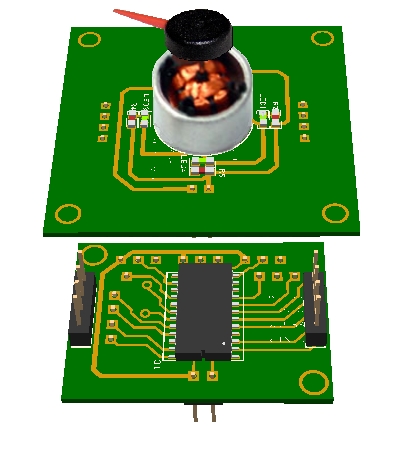
To hold the aircore you can use your own board or the new Aircore PCB wich will fit in a 40x40 mm instrument. The Aircore Controller pcb can be attached at the bottom side of the Aircore board without any extra wiring by means of two connectors.
You can see both here:

You can, then, wire the second aircore from the Aircore Controller pcb.

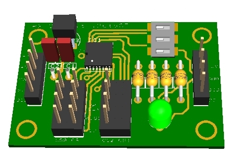
To drive the Aircore Controller you will also need the I2CtoSPI pcb. This board is able to drive up to 4 SPI devices and, apart of the aircores, can be used in the future to drive other SPI devices like, for example, the OLED display:


In this way, PSCockpit software will be able to drive up to 8 I2CtoSPI boards, which mean 34 Aircore controllers, which mean 68 (360º) aircores and 102 (90º) actuators.

In summary, for the engine instruments (OIL, NOZ POS, RPM and FTIT) you will need one I2CtoSPI board and two Aircore Controller pcbs for full 360º aircores.

Hope you like it!!
More info about the ICP board to come.

Regards,
Shep

Monday, October 21, 2013

PSCOCKPIT SYSTEM 3rd RUN!

PSCockit System keeps growing with new additional boards:
- ICP pcb
- Adafruit 16 servo controller
- Simco Aircores pcbs
- Vibration motors pcb
- I/O Enhancement pcb


Now, time to launch a third run!!!!
Description
For people who don’t know the system, the PSCockpit system has been developed with the following objectives:
- One stop hardware and software for cockpit systems. Once the cockpit is connected you can configure the software individually for each sim.
- Easy configuration and setup for people with out electronic knowledge.
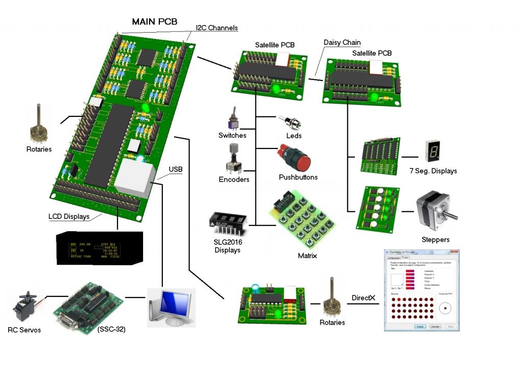
- Avoid excessive wiring runs along the cockpit: The system uses small satellite PCB’s that can be distributed along the cockpit. The communication between these satellite PCB’s and the Main PCB is done with only 2 wires (I2C protocol) plus the power cables. These wires can be connected in daisy chain. The idea is to wire each of the cockpit panels to only one satellite PCB.

GUIDES:
For more information about the system, please look at the following links:
- PSCockpit first run post: http://viperpits.org/smf/index.php?topic=7237.0
- PSCockpit second run post: http://www.viperpits.org/smf/index.php?topic=8679.0
- PSCockpit Quick Guide V2: http://www.mediafire.com/view/o7k6hvkt0y671iq/QuickGuideV2.pdf
- PSCockpit distribution example: http://www.mediafire.com/download.php?crkrwvt9csg92ri
- All "How to's" in a row at http://psfalcon.blogspot.com.es/search/label/PS%20Cockpit%20PCB%20System

SOFTWARE DOWNLOAD:
- PSCockpit Software Installation: http://www.mediafire.com/download.php?d80terg9airfhd2
- PSCockpit Softwate update v.0.9.3:
http://www.mediafire.com/download/mb5muokuzubct2v/PSCockpit093.rar

To install de update just copy the files to the installation directory.

Prices
The prices of the PCB’s already mounted and tested are the following:
- Main PCB: 60 €
- Digital expander for 40 inputs/outputs: 33 €
- Digital expander 16 inputs/outputs: 10 €
- Steppers/Other voltage outputs pcb: 28 €
- 7 segment displays pcb for 6 displays: 18 €
- Analogue pcb for 4 inputs/ 1 output: 20 €
- Yellow OLED display (85mm x 40mm), 256x64 for DED: 55 €
- ICP pcb: 60€
- I2CtoSPI pcb: 25€
- Aircore Controller pcb: 24€
- Aircore pcb: 15€
- Vibration Motors pcb: 38€
- I/O Enhancement pcb: 6,5€

- Shipments: 15€ / 25€ depending on the total weight order

More information about latest PCBs to follow!!

Time Line
- Orders will be accepted until Nov. 4th.
- Only direct bank transfers will be accepted. Sorry for the inconvenience.
- Delivery: December and January.


Regards,
Shep
Tuesday, August 13, 2013

PS Keys v.2.0

You can download new version of PSKeys as per Dunc recommendations here:
PSKeys v.2.0 Setup

Thanks Dunc!!

Regards,
Shep
Monday, July 8, 2013

HOW TO Assign Commands Directly From your BMS .key File

Now you can assign commands to your hardware directly from your BMS .key file in the PSCockpit Software v.0.9.1.

To do this, go to Command Page and select “BMS .key file” from the Keyboard menu. Click on Load to open your BMS .key file and you will see the list of all the callbacks already assigned. When you click on one of them, the software will read and display the key combination. To assign it to one of your switches, pushbuttons, etc, just click on Replace.


Edited on April 10th, 2016
------------------------------------------------------------------------------------------------------------------------
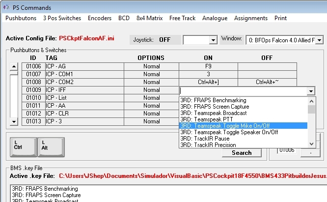
From version 0.9.9 you can also assign commands from a drop down list directly in the element matrix by clicking on it with the right button of the mouse once you have loaded the .key file:


------------------------------------------------------------------------------------------------------------------------

Regards,
Shep
Saturday, June 29, 2013

HOW TO use Adafruit 16-Channel Servo Driver with the PS Cockpit System

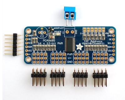
Now the PSCockpit System can drive the Adafruit 16-Channel Servo Driver:


For more information, check http://www.adafruit.com/products/815

You have to consider the following details:
- The Adafruit board is non compatible with the SSC-32 board for servos. You can only use only one of the system at once.
- Only 2 Adafruit boards can be connected to the PSCockpit System.
- Adafruit boards have to be connected only to the Main I2C Channel of the Main Board.
- The firmware of the Main Board has to be updated to version 1.4.0
- PSCockpit software must be version 0.9.1 or higher
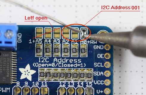
- I2C address of the Adafruit board has to be selected with the 3 less significant digits, the other 3 must remain open:


The wiring is as follows:

Main Board Main I2C Channnel ---> Adafruit
5V+ ---> VCC
GND ---> GND
SCD ---> SDA
SCL ---> SCL

To power the servos use the terminal block of the Adafruit board.

Read carefully the Adafruit datasheet for assembly, adding a capacitor and other things.

Configuring the Adafruit board

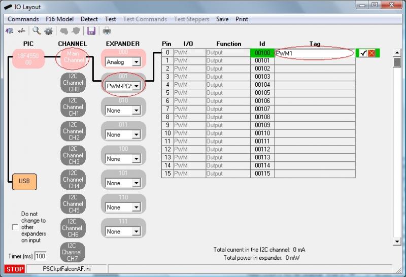
To configure the system we have to add the Adafruit board. Open the IO Layout page of the PSCockpit software and select PWM-PCA9685 on the expander dropdown list of the Main I2C channel. You will see the list of PWM outputs available for the Adafruit boards. In the tag section you can put the name of each device:


Note: Adafruit board can only be used on the Main Channel.

Once you have attached the Adafruit board to the Main I2C Channel you can click “Detect”. This action will detect and configure the Adafruit board. If everything is correct the PWM-PCA9685 expander will appear in pink.

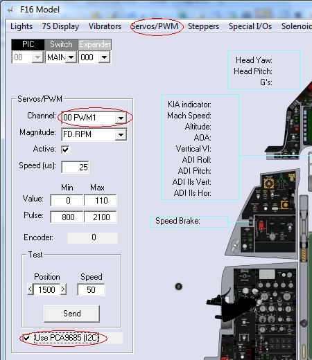
To select the Adafruit board to be used instead of the SSC-32 for servos, go to F16Model and select Servos/PWM page. You will see “Use PWM-PCA9685” checkbox. Once you check it, the servo channels dropdown list will be filled with the tags configured in the IOLayout:


To configure and to add scales, see steps 6 and 7 in the following post: How to use Aircores

Regards,
Shep

Wednesday, April 10, 2013

HOW TO Connect and Configure your OLED 256x64 display

Edited on Aug, 17th, 2022:
-------------------------------------------------------------------------------------------------------------------------
For 11th Run displays see this post: v2 OLED display
-------------------------------------------------------------------------------------------------------------------------

The OLED display is supplied with a driver board attached to the display pcb. This driver board has a voltage regulator to convert the 5V to 3,3V, which supply power to the OLED display and two signal converters to convert 5V signals coming from the Main Pcb to 3,3V signals going to the display.

The OLED is configured to be used as 6800 Parallel 8 bit interface.

Before connecting the OLED display turn off the power supply of the Main Pcb and detach the USB cable from the computer.

Edited on Feb, 18th, 2014:
------------------------------------------------------------------------------------------------------------------------
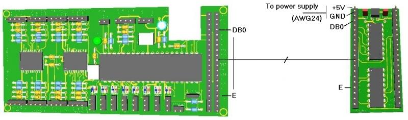
Make a cable with 20 wire and connect straight pin to pin:
Be sure you have firmware version 1.5.0 or higher (1.5.1 recommended) in the Main PCB. You can see your firmware version by clicking on Help/About in the PSCockpit Software)
Make a cable with 14 wires and connect it from pin DBO to E.
Power the board directly from the power supply separately from the signals cable with SWG24 wires (thicker that the normal paralel strips used in PC connections).
------------------------------------------------------------------------------------------------------------------------


Not all the wires/pins are used for this display. If you want to make a cable with less wires, these are the pins used: +5V, GND, DB0, DB1, DB2, DB3, DB4, DB5, DB6, DB7, RST, R/W, Rs, and E.

Turn on power and connect the USB cable to your computer.

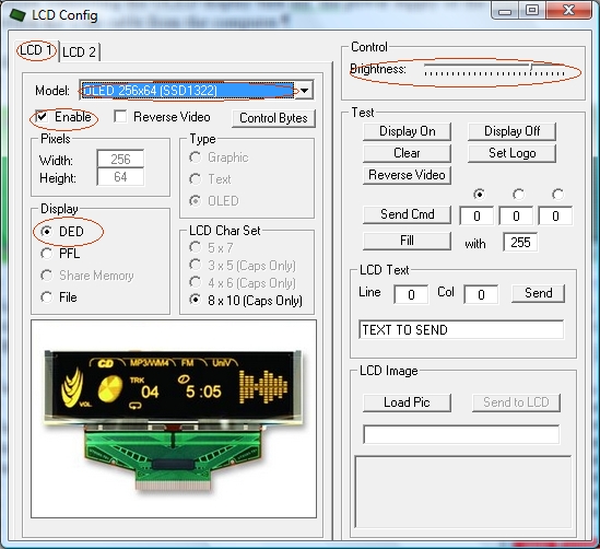
Run PSCockpit software and go to the LCD page and select the OLED display on the drop down list in the corresponding LCD tab. LCD 1 is used for the LCD connected to the most external connector of the Main Pcb and LCD 2 for the inner connector:


Don’t forget to check “Enable” and the “DED” or “PFL” to use with our sim and the desire brightness of the display with the slider bar.

In “Test” area you have some usual commands for you to try. They are self explanatory.

This display accepts 3 bytes commands. Select the corresponding option button above the commands text box to send one, two or three bytes.

You can also send monochrome bitmaps to the OLED but the horizontal length of the bitmap has to be multiple of 4.

NOTES:
* The OLED display is activated only when you enter PSCockpit software and is deactivated when you exit the program. This is to avoid image persistence on the OLED.

* The OLED display may be light sensitive. Caution should be taken to avoid exposure of this device to any light source during normal operation.

* The OLED display is not radiation protected.

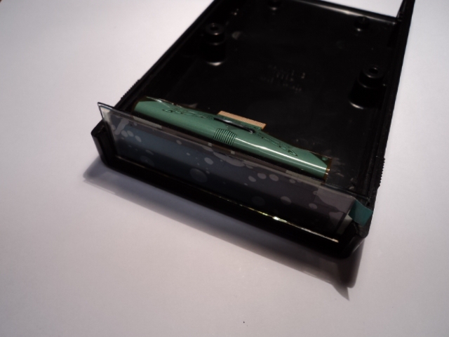
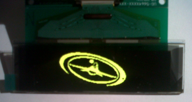
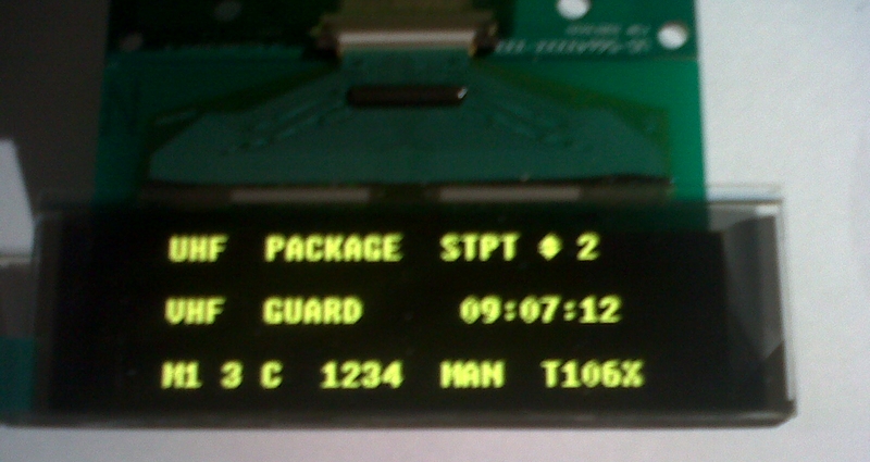
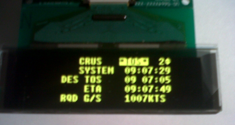
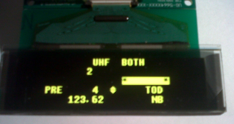
Some pictures of the running OLED display:


Kind regards,
Shep
Monday, March 11, 2013

HOW TO Install your 256x64 OLED Display into the DED box

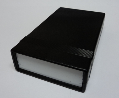
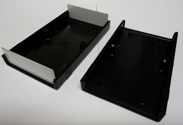
The box I have selected is from Hammond Manufacturing, part number 1598ABK. It comes with two detachable front and rear aluminium plates:


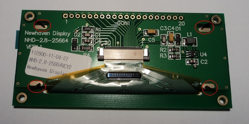
To fit the display into the box we have to disassemble the OLED display, make some modifications of the OLED pcb and make some adjustment in the box.
Please follow the follow the steps carefully:

1. Unbend the 4 little flanges of the aluminium frame of the OLED display


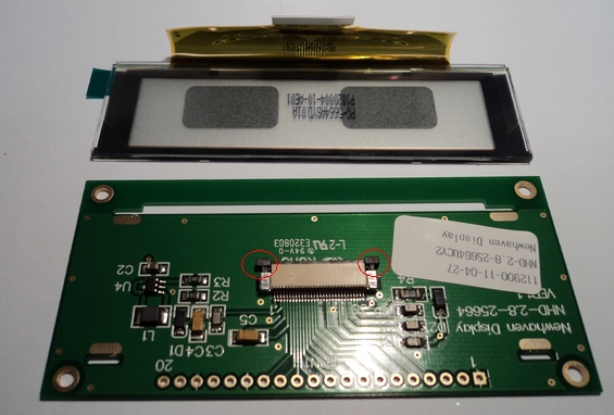
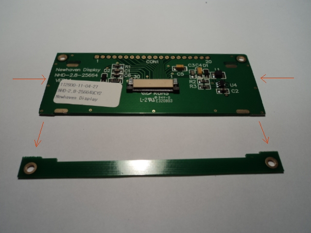
2. Detach the aluminium frame from the pcb and then detach the crystal from the aluminium frame by pressing carefully the crystal from both ends. There is also a plastic protector attached to the crystal and frame. Remove it from the frame and stick it again to the OLED crystal:


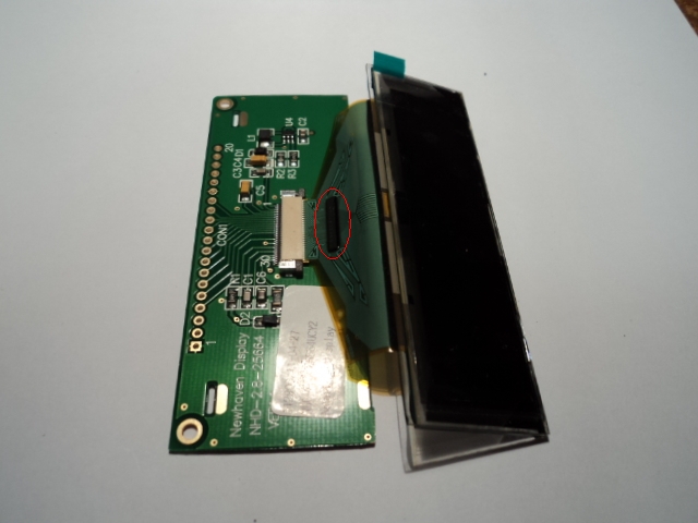
3. Remove the crystal ribbon from the pcb by gently pushing out the two flanges of the connector:


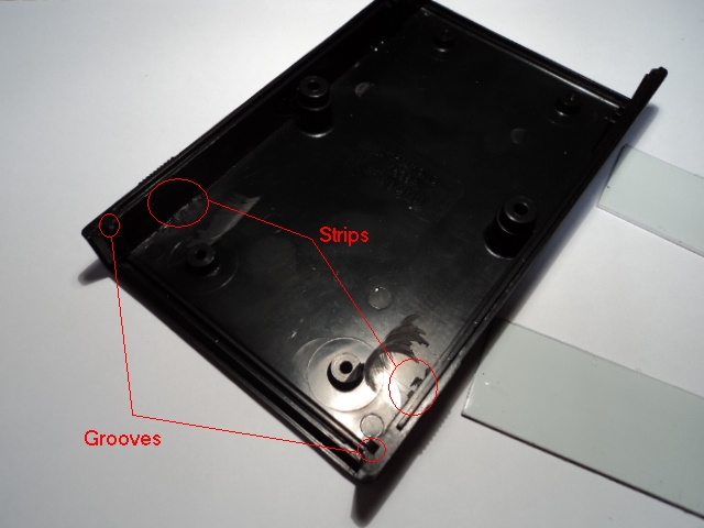
4. Now, if you try to insert the crystal into the front groove of the box, you will notice that the crystal doesn’t enter smoothly. The groove of the box has to be enlarged a little with a cutter. Also the little strips of the internal face of the box have to be removed. The modifications of the grooves have to be done in both parts of the box while the strips can be removed in only one part of the box.


5. Now the crystal can be inserted in the box:


6. To allow the OLED display pcb get inside the box, cut the bottom side of the PCB wich has no copper nor elements and reduce a little the sides of the pcb with the sandpaper:


7. Attach again the crystal to the pcb. The little chip of the ribbon has to be on top:


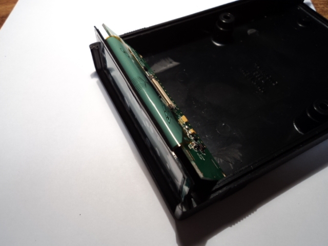
8. Place the crystal and the pcb in the box:


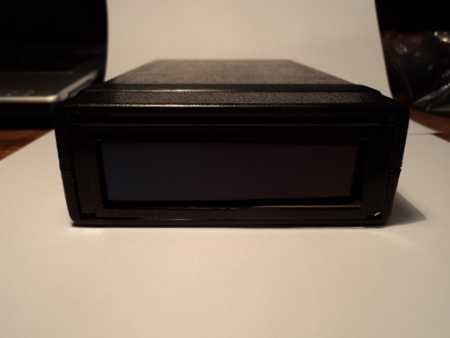
9. Close the box carefully with the top part:


You can even reuse the aluminium frame with some modification:

Coming soon……. connecting the OLED display. :taz:

Kind regards,
Shep

Wednesday, February 6, 2013

New Encoder Interface Option of the PSCockpit System

As explained before, you can connect incremental encoders to the PSCockpit System to emulate some rotaries of the real cockpit. The digital signals coming from the encoders are checked every PSCockpit Software cycle time. This means that if you move too fast the encoder or you have encoders with more than 12 signals of resolution; the software is not able to catch up the electric signals thus the commands sent to the sim may not be accurate or slow.

To resolve this problem, now you can use the encoders as if they were a single pushbutton: in one rotational direction, sending a selected command to the sim and sending a different command in the reverse rotational direction by holding a desired pushbutton of your joystick:


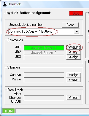
To do this, first, with your favourite Joystick connected, go to the Joystick Page of the PSCockpit Software, select the device in the “Joystick device number” dropdown list and click on the corresponding “Assign” button. Now, press the joystick button you want to be assigned. In example, I have assigned the Joystick button 1 to the PSCockpit JB1:


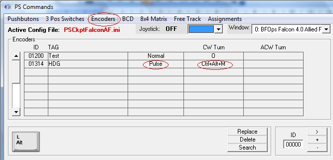
Go to the Commands page of the PSCockpit Software and select the “Encoders” tab. Select “Pulse” function in the HDG encoder and assign the desired key combination:


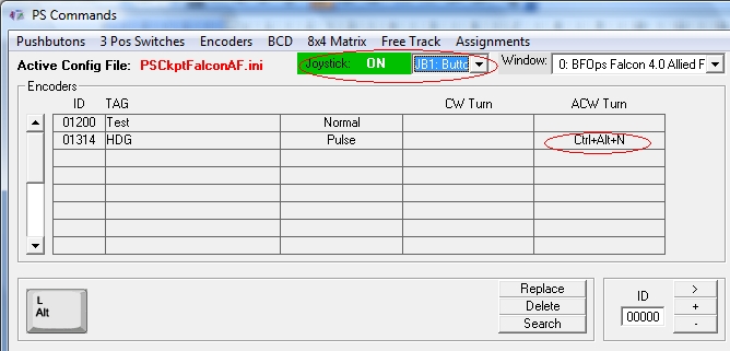
Now, press the joystick button or select the JB1 from the dropdown list “Joystick” and assign the key combination to the ACW Turn field:


Remember: in the PSCockpit System you can program 3 joystick buttons and assign a different key combination for each button. This can be made in all the inputs elements connected to the PSCockpit boards. Also you can define at what window you want to send that command in the “Window” dropdown list.

Kind regards,
Shep

Thursday, January 24, 2013

OLED Display for PSCockpit System

 Yihaw ! Display driver for the 256x64 OLED driver already implemented: Yihaw !


Regards,
Shep
Sunday, January 13, 2013

PS COCKPIT PCBs SECOND RUN!!!

Time to launch second run of the PSCockpit PCB´s with the new additional analogue board for rotaries!!!

Description
For people who don’t know the system, the PSCockpit system has been developed with the following objectives:
- One stop hardware and software for cockpit systems. Once the cockpit is connected you can configure the software individually for each sim.
- Easy configuration and setup for people with out electronic knowledge.
- Avoid excessive wiring runs along the cockpit: The system uses small satellite PCB’s that can be distributed along the cockpit. The communication between these satellite PCB’s and the Main PCB is done with only 2 wires (I2C protocol) plus the power cables. These wires can be connected in daisy chain. The idea is to wire each of the cockpit panels to only one satellite PCB.

For more information about the system, please look at the following links:
- PSCockpit firs run post: http://viperpits.org/smf/index.php?topic=7237.0
- PSCockpit Quick Guide: http://www.mediafire.com/view/?6kacpd31w3bvvve
- PSCockpit distribution example: http://www.mediafire.com/download.php?crkrwvt9csg92ri
- All "How to's" in a row at http://psfalcon.blogspot.com.es/search/label/PS%20Cockpit%20PCB%20System

Prices
The prices of the PCB’s already mounted and tested are the following:
- Main PCB: 60 €
- Digital expander for 40 inputs/outputs: 33 €
- Digital expander 16 inputs/outputs: 10 €
- Steppers/Other voltage outputs pcb: 28 €
- 7 segment displays pcb for 6 displays: 18 €
- Analogue pcb for 4 inputs/ 1 output: 20 €
- Yellow OLED display (85mm x 40mm), 256x64 for DED: 55 €
- Shipments: 15€ / 25€ depending on the total weight order

Time Line
- The run will be cancelled if there are less than 10 people.
- Orders will be accepted until Feb. 3rd.
- Payments to be done since there are 10 people until Feb. 10th. Sorry for the inconvenience but only direct bank transfers will be accepted.
- Deliveries: 4-5 weeks from the end of the run.

Complete Panels
If you don’t care to have real pushbuttons, switches and leds in you panels, I can provide you with low cost panels, already wired, configured, tested and ready for backlight alone with the PSCockpit system:


For prices and delivery dates for the panels, please send me a PM with your requirements.

Regards,
Shep
Monday, November 19, 2012

PSCockpit System Firmware v.1.2 Update

I have modified the firmware of the PSCockpit Main Board to correct some bugs and to add the future analogue expanders functionality. You don’t need to update the firmware if you are not affected.

Firmware v.1.2 Change Log:

- Corrected bug not able to read inputs from expanders connected to channels 4 to 7. This bug only applies on early versions of the firmware. I will send a PM to those people that should apply the firmware update because of this reason.

- Corrected bug of commands sent to sim after "First read". This bug was only affecting the 40I/O expander.

- Included new functionality to read analog expanders connected to Main Channel.


The firmware update can only be done with Windows XP/Vista operating system.

Download the file here http://www.mediafire.com/download.php?bjigkkydd15dntz, unrar into any folder and follow the instructions of the file FirmwareUpdate.pdf.

Regards,
Shep
Monday, October 22, 2012

New PS UDP Setup File

For the ones who are having problems installing PS UDP in your computer, specially Windows 7 users, I have improved the installation Setup program. Hope it helps!

You can download all the files for PSUDP here: PSUDP

Installation notes:
- Unrar the file
- Install PS UDP in your computer with PSUdpSetUp.exe
- Install PSGauges.apk in all your favorite android devices
- Enjoy

Regards,
Shep

Monday, October 8, 2012

Version 0.8.0.2 of the PSCockpit Software

PSCockpit v.0.8.0.2 Changelog

- "IOCARD 7SEG DISPLAYS NOT CONFIGURED" message removed
- Aux Tacan Channel 7 segment diaplays now working
- UFC Tacan Channel 7 segment displays now working
- Added one digit to UFC Tacan channel --> 0 = Channel X, 1 = Channel Y
- Added one digit to Aux Tacan channel --> 0 = Channel X, 1 = Channel Y
- Added X and Y UFC Tacan channel outputs for alphanumeric display
- Added X and Y Aux Tacan channel outputs for alphanumeric display
- Added aux tacan channel in syncrho with sim
- Altitud mB now working
- Fixed steppers now working on 40 I/O board
- 4-Digit 5x7 Dot Matrix Alphanumeric Intelligent Display SLG2016 implemented
- Key input directly from keyboard in Command page
- English (US) keyboard added for commands
- Added Falcon and hexadecimal key codes for commands
- Added 8x4 pushbuttons matrix functionality
- Added PCF8591P analog I2C inputs/outputs funcionality
- Fixed a problem with serial the interface RS232 when loading .key

You can download it at http://www.mediafire.com/download.php?ng9j471cxon03nq

To install this new version the old version must be installed. Just unrar the files an put them in your PSCockpit directory.
If you need to register the FSCSC.ocx in windows, double click on the fsdt_32bit.reg for 32 bits OS or fsdt_64bit.reg for 64 bits OS.

Kind regards,
Shep

Saturday, September 22, 2012

HOW TO Implement the Magnetic Held Switches in the PSCockpit System

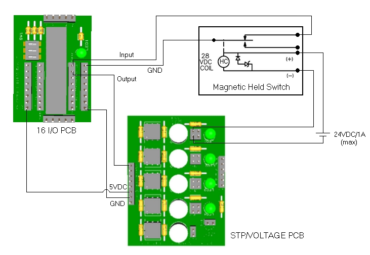
Some of the switches of our cockpit may have electric coils to hold the contact of the switch at a certain position. When the coil is deactivated the switch returns to the OFF position.

This behaviour is easily implemented with the PSCockpit System. We will need to wire the contact of the switch to a I/O Satellite Pcb and the coil to a Stp/Other Voltages Pcb as the coil will need other voltage and more current to activate. The electric schema could be the following:

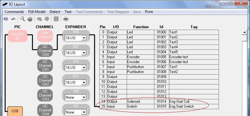
 The configuration of this wiring in the PSCockpit Software is the following:


You can easily test the circuit (input and output individually) in Test mode.

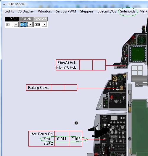
In order to link the switch with its coil, go to the F16 Model and select the Solenoids page. Enter the corresponding switch and coil Id´s:


Of course, you want the switch to send the keystroke to the sim, so, go to Commands page and configure the switch:


Now, when the switch is activated, the command will be sent to the sim and the coil will be energized. Depending on the switch function, the coil will be deactivated by the PSCockpit Software when in Run mode.

Edited on April, 10th, 2016
--------------------------------------------------------------------------------------------------------------------------
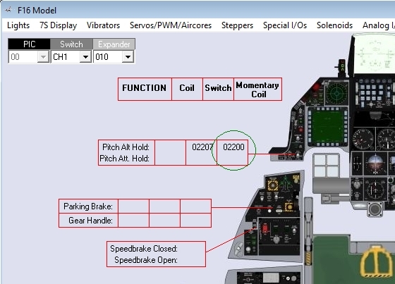
For homemade magnetic switches -the ones which needs only momentary energy to set back the switch to the original position- you have to set the coil output in the field called "Momentary coil":


The momentary coil output works as follows:
- Switch is activated ---> momentary coil remains de-energized
- Condition to return switch to original position is met ---> momentary coil is energized
- Switch returns to original position by means of the coil ---> momentary coil is de-energized

Of course, is you return the switch to the original position manually, the momentary coil is never energized.
---------------------------------------------------------------------------------------------------------------------

Regards,
Shep