
Saturday, April 30, 2016
New PScockpit System Pcbs Distribution for the F16 Block 52
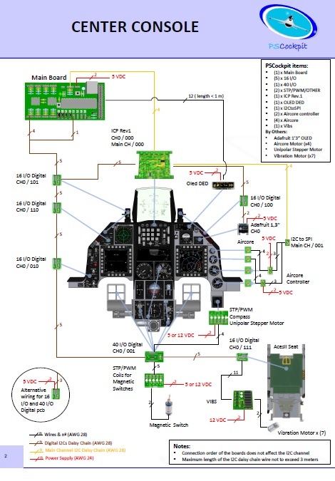
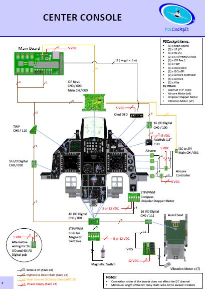
New PScockpit System pcbs distribution for the F16 Block 52, now in pdf format:
Sunday, April 17, 2016
PS Cockpit Software V.0.9.9 Update
The new version V.0.9.9 auto installable version of the PS Cockpit Software is available for download!!
PS Cockpit Software V.0.9.9 Changelog:
- JFS magnet driven by JET_FUEL_STARTED bit (BMS4.33)
- Added "software switch" function for analogue inputs (Commnands)
- Added "software encoder" fuction for analogue inputs (Commands)
- Added all the lights for TWA and TWP (F16 Model)
- Corrected the TWA and TWP lights to work as BMS 4.33 manual, including the flashing modes
- Corrected analogue bars when testing aircores (IOLayout)
- Added momentary coils for homemade magnetic switches (Airplane Models: Solenoids)
- Added speedbrakes solenoids (F16Model: Solenoids)
- Added UHF Off bit driven by OFF selector and COMM1 switch (Airplane Models: Special I/Os)
- Added CMDS pcb and ICP Rev1 pcb description (QuickGuideV4)
- Added warning on the IOLayout page about the issue that the stepper motors have to be connected in certain expander ranges (IOLayout)
- Changed overcurrent and overpower warnings to not consider expanders changed to "None" (IOLayout)
- Added Enter, Del, Escape, Page Up and Page Down keyboards inputs in the IOLayout for better eficiency (IOLayout)
- Added warning before going into RUN mode if the sim window name where to send commands hasn't been defined (PSCockpit)
- Removed warning when changing the sim and the airplane model is the same (PSCockpit)
- Added dropdown list with BMS callbacks. Now you can assign commands directly from the BMS callbacks with a left clik of the mouse on a given position in the list of switches, pushbuttons,.. (IOLayout)
You can download it at: Download
To update the firmware of the Main Board, visit: PS Cockpit Firmware Update
Thanks all for your patient!!!
Regards,
Shep
Monday, April 11, 2016
HOW TO Configure the CMDS Panel
For CMDS Board description, options and how to configure the expander address, see PSCockpit Quick Guide V.4 – CMDS PCB. You can access the Quick Guide from Help/Quick Guide menu in the PSCockpit software.
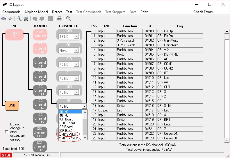
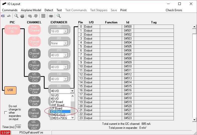
To configure the PSCockpit CMDS panel select the correct option from the Expander pull down list in the IOLayout page of the PS Cockpit Software at the correct I2C channel depending of your hardware:
- CMDS+SLG if you have SLG2016 displays in your CMDS pcb
- CMDS+7Seg if you have 7 segment displays in your CMDS pcb
In case of there is some data already in the selected expander, the software will prompt you for continue:

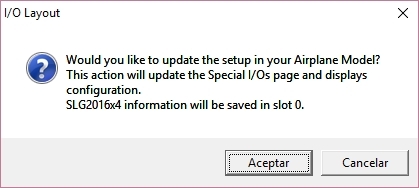
The software will prompt you to setup the SLG2016 or 7 segment displays in our Airplane model:
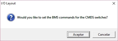
The software will also prompt you to add the standard BMS commands for the CMDS:
To configure the PSCockpit CMDS panel select the correct option from the Expander pull down list in the IOLayout page of the PS Cockpit Software at the correct I2C channel depending of your hardware:
- CMDS+SLG if you have SLG2016 displays in your CMDS pcb
- CMDS+7Seg if you have 7 segment displays in your CMDS pcb
The software will prompt you to setup the SLG2016 or 7 segment displays in our Airplane model:
The software will also prompt you to add the standard BMS commands for the CMDS:
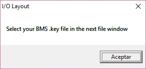
If you accept, the software will prompt you to search for your BMS .key file and will automatically search for the key strokes you have set in your .key file for the CMDS:
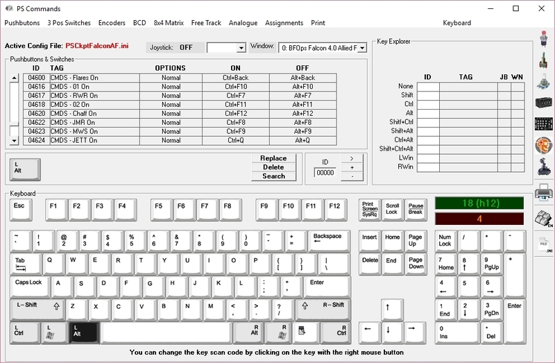
If any of the commands hasn't been set you will see a warning indicating how many commands haven't been set and the Commands page of the PSCockpit software will appear:
Once the CMDS panel is already configured you can modify the list of inputs/outputs as desire as well as the free I/O of the expander:

If any of the commands hasn't been set you will see a warning indicating how many commands haven't been set and the Commands page of the PSCockpit software will appear:
HOW TO Configure the ICP Rev1 Panel
For ICP Rev1 Board description, options, and how to configure the expander address, see PSCockpit Quick Guide V.4 – ICP REV1 PCB. You can access the Quick Guide from Help/Quick Guide menu in the PSCockpit software.
Digital I/Os
To configure the PS Cockpit ICP Rev1 panel just select ICP Rev1 Board from the Expander pull down list in the IOLayout page of the PS Cockpit Software at the correct I2C channel and expander configured in your ICP Rev1 board (see PSCockpit Quick Guide V.4 – ICP Rev 1 PCB):
In case of there is some data already in the selected expander, the software will prompt you for continue:
If you accept, the software will prompt you to search for your BMS .key file and will automatically search for the key strokes you have set in your .key file for the ICP:
If any of the commands hasn't been set you will see a warning indicating how many commands haven't been set and the Commands page of the PSCockpit software will appear:
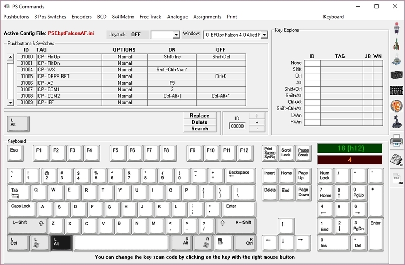
Once the ICP panel is already configured you can modify the list of inputs/outputs as desire as well as the free I/O of the expander:

Be aware that once the configuration is saved, whenever you enter the IOLayout Page you won’t see “ICP Rev1 Board” label on the expander anymore but the 40 I/O label.
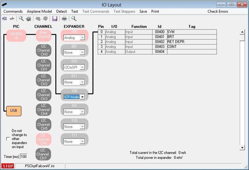
Analogue inputs
You have to repeat the process for the analogue inputs by selecting “ICP Analogue” in the I2C Main Channel:
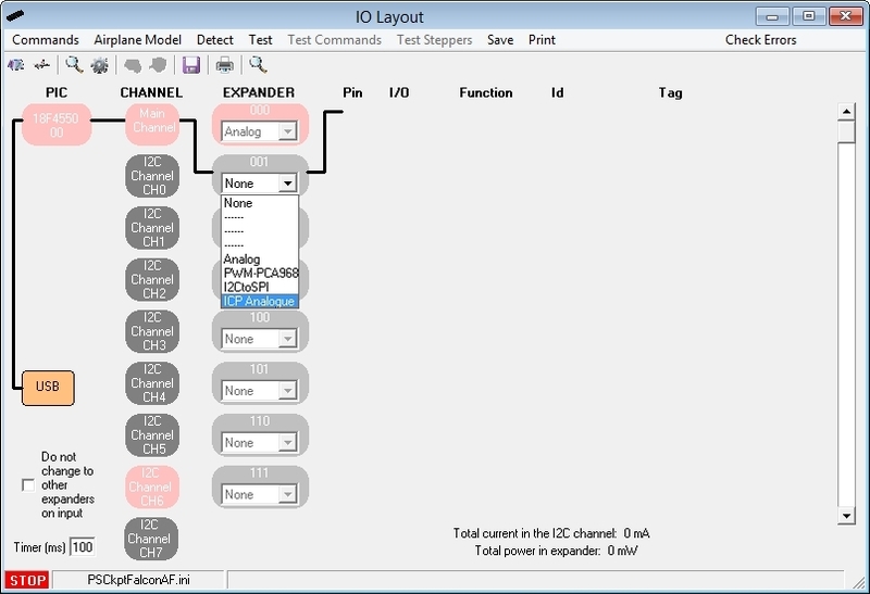
The expander will be configured as shown:
Digital I/Os
To configure the PS Cockpit ICP Rev1 panel just select ICP Rev1 Board from the Expander pull down list in the IOLayout page of the PS Cockpit Software at the correct I2C channel and expander configured in your ICP Rev1 board (see PSCockpit Quick Guide V.4 – ICP Rev 1 PCB):
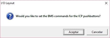
If you accept, the software will prompt you to search for your BMS .key file and will automatically search for the key strokes you have set in your .key file for the ICP:
Once the ICP panel is already configured you can modify the list of inputs/outputs as desire as well as the free I/O of the expander:
Be aware that once the configuration is saved, whenever you enter the IOLayout Page you won’t see “ICP Rev1 Board” label on the expander anymore but the 40 I/O label.
Analogue inputs
You have to repeat the process for the analogue inputs by selecting “ICP Analogue” in the I2C Main Channel:
The expander will be configured as shown:
Sunday, April 10, 2016
HOW TO Assing Keystrokes in PSCockpit System (COMMANDS)
One of the most important thing is how to interface the inputs of the cockpit (switches, encoders, BCD,...) with the sim. In the PSCockpit system, this interface is made by means of sending key strokes to the sim window once one input has changed its previous status.
The key stroke sequence to be sent to the sim is defined in the Command page of the PSCockpit software. To set an specific command for each physical input element, follow this procedure:
You can change the keyboard to English/Spanish by clicking on Keyboard.
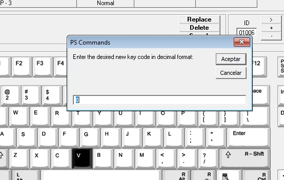
If you have another keyboard or the key is not working correctly in your sim, you can reassign the control code of the key by clicking on the desired key with the right button of the mouse. A box will appear asking for the new key code in decimal format:
For Falcon BMS sim users, the key file (.key) can be loaded by clicking on "BMS Key File".
You can read the procedure in the following post: HOW TO Assign Commands from Falcon BMS Key File
KEY STROKE OPTIONS
Some of the input devices have key stroke options. The explanation of those is the following:
Pushbutton and Switches:
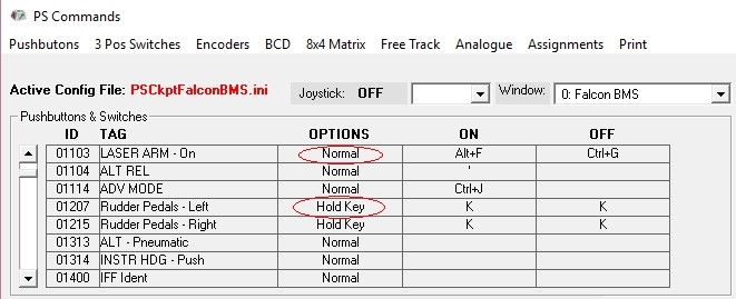
- Normal: Each time the input is activated the ON key stroke sequence is sent to the designated window. Each time the input is deactivated the OFF key stroke sequence is sent to the designated window.
- Hold key: The stoke sequence is sent continuously until the input is deactivated. You must stablish the same key stroke sequence in either ON and OFF fields.
3 Pos Switches:
- POS 1: When the 3 position switch is activated in position 1 the key stroke sequence is sent to the designated window.
- POS 2: When the 3 position switch is activated in position 2 the key stroke sequence is sent to the designated window.
- CENTER: When the 3 position switch is deactivated (center position) the key stroke sequence is sent to the designated window.

Encoders:
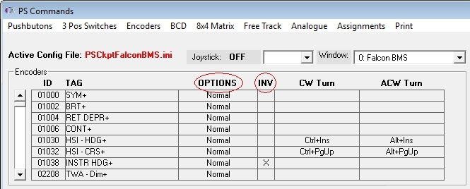
- Normal: When the encoder is rotated clockwise direction, the key stroke sequence under CW Turn will be sent to the designated window. Likewise, when the encoder is rotated counterclockwise direction the key stroke sequence under CCW Turn will be sent to the designated window
- Pulse: Reserved for future use.
- INV: When the INV tick is checked, the key stroke sequence sent to the designated window will be the opposite of the turning direction. This option allows to avoid rewiring of the encoder in case is reversed.
Analogue Inputs
When using pots in the PSCockpit system you can modify their behavior by selecting one of the following options:
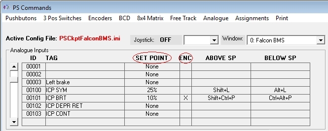
- SET POINT: By selecting a set point, a single key stroke sequence under Above SP will be sent to the designated window whenever the set point is bypassed by the analogue signal. Likewise, a single key stroke sequence will be sent to the designated window whenever the analogue signal goes under the stablished set point. The set point options are 5%, 10%, 25%, 50%, 75%, 90% and 95% of the analogue input total scale. This feature is useful to replicate by software the on/off switch functionality for pots with no such switch.
- ENC: By ticking the ENC check box, the pot will act as an encoder, sending the key stroke sequence under Above SP to the designated window each time the analogue signal bypass the amount in % established in the Set Point. Likewise, the Below SP key stroke signal will be sent to the designated windows whenever the analogue signal lower that amount in %.
Kind regards,
Shep
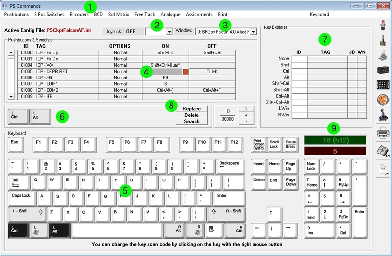
The key stroke sequence to be sent to the sim is defined in the Command page of the PSCockpit software. To set an specific command for each physical input element, follow this procedure:
- Select type of input element (pushbutton, switch, ...) by clicking in the upper menu.
- Select the joystick DX pushbutton in the dropdown list if you want to want to send a different key stroke combination while pressing the joystick button. If you want to send the key stroke combination without pressing any DX pushbutton of your joystick, select blank from the drop down list.
- Select the Window name of the application you want to send the key stroke combination to. To fill the name list of application windows read the following post: HOW TO Assign Key Strokes to Different Applications. Of course, the most important window name will be your favorite sim!.
- Select the position inside the matrix in which you want to place the key combination. A grey field will appear on that position.
- Select the key stroke combination by clicking on the keyboard or directly from your keyboard.
- The key stroke combination will appear in the middle frame.
- You can review in the Explorer frame if you have already assigned the key stroke.
- Click on "Replace" and the key combination will be transferred to the selected position of the matrix. If you click on "Delete" the key stroke combination will be deleted from the selected position of the matrix. If you click on "Search" the key combination will be searched in the matrix and if it is found in any position, it will be showed in the first line of the matrix.
- You can see the decimal and hexadecimal values of the key in the green frame and also the key codes for Falcon in the orange frame where you can copy by clicking on it.
If you have another keyboard or the key is not working correctly in your sim, you can reassign the control code of the key by clicking on the desired key with the right button of the mouse. A box will appear asking for the new key code in decimal format:
You can read the procedure in the following post: HOW TO Assign Commands from Falcon BMS Key File
KEY STROKE OPTIONS
Some of the input devices have key stroke options. The explanation of those is the following:
Pushbutton and Switches:
- Normal: Each time the input is activated the ON key stroke sequence is sent to the designated window. Each time the input is deactivated the OFF key stroke sequence is sent to the designated window.
- Hold key: The stoke sequence is sent continuously until the input is deactivated. You must stablish the same key stroke sequence in either ON and OFF fields.
3 Pos Switches:
- POS 1: When the 3 position switch is activated in position 1 the key stroke sequence is sent to the designated window.
- POS 2: When the 3 position switch is activated in position 2 the key stroke sequence is sent to the designated window.
- CENTER: When the 3 position switch is deactivated (center position) the key stroke sequence is sent to the designated window.
Encoders:
- Normal: When the encoder is rotated clockwise direction, the key stroke sequence under CW Turn will be sent to the designated window. Likewise, when the encoder is rotated counterclockwise direction the key stroke sequence under CCW Turn will be sent to the designated window
- Pulse: Reserved for future use.
- INV: When the INV tick is checked, the key stroke sequence sent to the designated window will be the opposite of the turning direction. This option allows to avoid rewiring of the encoder in case is reversed.
Analogue Inputs
When using pots in the PSCockpit system you can modify their behavior by selecting one of the following options:
- SET POINT: By selecting a set point, a single key stroke sequence under Above SP will be sent to the designated window whenever the set point is bypassed by the analogue signal. Likewise, a single key stroke sequence will be sent to the designated window whenever the analogue signal goes under the stablished set point. The set point options are 5%, 10%, 25%, 50%, 75%, 90% and 95% of the analogue input total scale. This feature is useful to replicate by software the on/off switch functionality for pots with no such switch.
- ENC: By ticking the ENC check box, the pot will act as an encoder, sending the key stroke sequence under Above SP to the designated window each time the analogue signal bypass the amount in % established in the Set Point. Likewise, the Below SP key stroke signal will be sent to the designated windows whenever the analogue signal lower that amount in %.
Kind regards,
Shep
Saturday, December 12, 2015
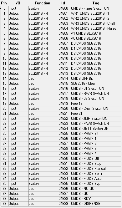
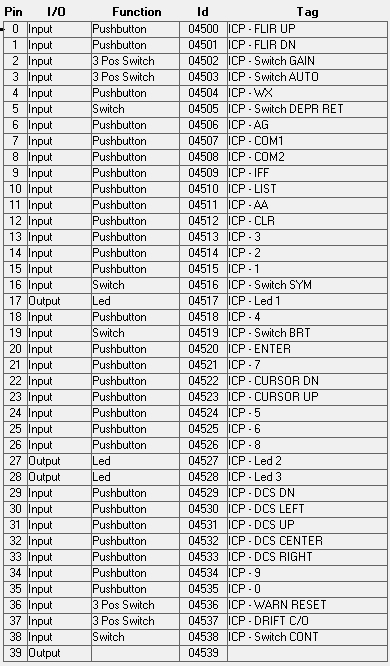
ICPRev1 and CMDS Boards Pinout
Hi everybody,
Some shimpents are on the way and I will ship the rest of your orders in the following two weeks.
For the ones that have already the ICPRev1 board, be aware that the current ICP configuration of the PSCockpit Software is not valid. The new one for ICPRev1 and CMDS boards will come with the next software revisión.
If any of you want to configure them by yourselves, here is the pinout of both boards:
Sunday, November 22, 2015
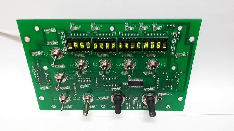
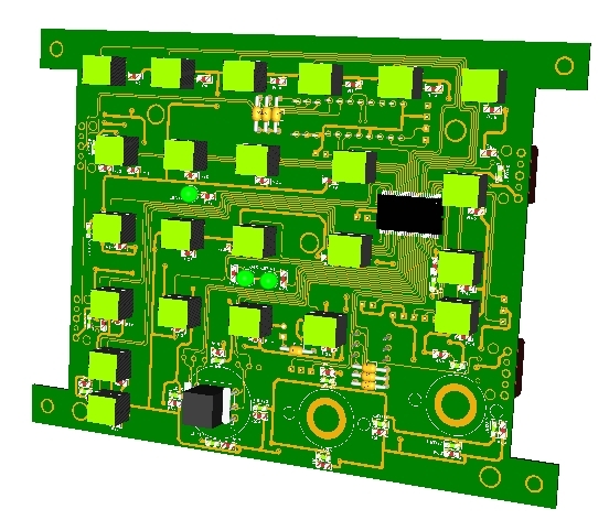
CMDS and ICP Rev1 Boards
Hello everybody!
Some pictures of the full CMDS and ICP Rev.1 boards already assembled:
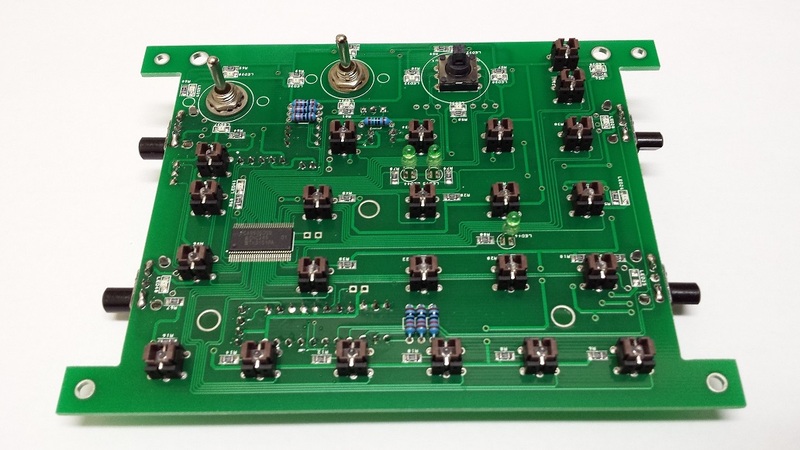
One note on the ICP Rev.1:
I found that the switch of the thumbwheel pots are located on the upper side of the thumbwheel so I've decided to replace them with normal pots. To simulate the switch I've added an option in the PSCockpit software.
Still some items and pcbs to be received this week but I will begin to deliver the boards next week.
Regards,
Shep
Some pictures of the full CMDS and ICP Rev.1 boards already assembled:
One note on the ICP Rev.1:
I found that the switch of the thumbwheel pots are located on the upper side of the thumbwheel so I've decided to replace them with normal pots. To simulate the switch I've added an option in the PSCockpit software.
Still some items and pcbs to be received this week but I will begin to deliver the boards next week.
Regards,
Shep
Monday, November 2, 2015
PSCockpit Quick Update for BMS 4.33
Hi everybody,
You can download versión 0.9.8 of the PSCockpit Software at: PSCockpit V0.9.8 Download
It is a quick Update executable for BMS 4.33!!
Just unzip and copy PSCockpit.exe to your PSCockpit directory.
CHANGELOG V 0.9.8 (WIP)
=====================
- Added BMS 4.33 new Shared Memory values: Altimeter barometric altitud, Altimeter pneumatic flag, Backup UHF channel and frequency, Cabin Pressure, Hydraulic Pressure A and B, Current time, Vehicle ACD.
- Added BMS 4.33 new Shared Memory Values to A10 Model: Fuelflow2, rpm2, ftit2, Oilpress2.
- Pitch and roll trim added to the F16 Model in the servo section.
- Added inverse POWER_OFF bits outputs
- Corrected bug in .key file modifiers (Commands)
- Added "Reset UI" command in the System Tray Menu to reset PSCockpit UI when it is not visible.
- Corrected a bug with arrow keys scan codes (Commands)
- Added the posibility to map your own key scan code (Commands)
Regards,
Shep
Friday, September 25, 2015
CMDS board
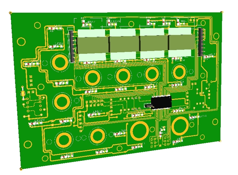
The following components are also inlcuded:
- (25) SMD leds for lettering backlight.
- (2) SMD leds for GO and NO GO indication.
- (3) SMD leds for DISPENSE READY indication
- (1) Rotary switch with 5 positions 45º
- (1) Rotary switch with 6 positions 30º
You will find the following elements in the backside:
- (1) Connector for backlight illumination.
- (1) Connector for digital I/O I2C channel,
- (1) Miniswitch to select digital I2C channel address
- (1) Connector for7 free digital I/Os of the 40 I/O board.
- (1) Selectable connector for dimmer/CMDS_OFF bit
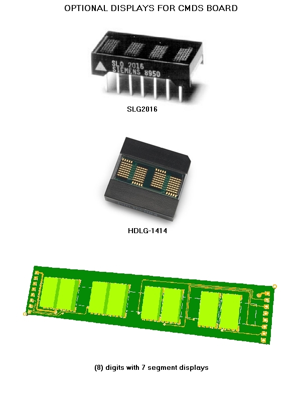
To complete the CMDS board, it can be supplied with the optional following elements:
- (8)Mini Toggle ON-OFF switches of 6 mm diameter. One of them comes with a locking lever for the JETT switch. Be aware that these switches are smaller than the real ones.
- SLG2016 displays, or
- HDGL-1414 displays, or
- 7 Segment display board with 8 digits of 4.22 x 7.62 mm
Tuesday, September 22, 2015
PSCockpit System 5th Run
Time to launch a new run of the PSCockit System!! 
In this run the following new boards have been developed:
- ICP pcb, revision 1.
- CMDS pcb
- CMDS 7 segment display digits
Description
- One stop hardware and software for cockpit systems. Once the cockpit is connected you can configure the software individually for each sim.
- Easy configuration and setup for people with out electronic knowledge.
- Avoid excessive wiring runs along the cockpit.
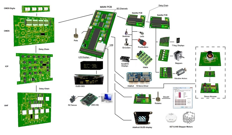
The system uses small satellite PCB’s that can be distributed along the cockpit. The communication between these satellite PCB’s and the Main PCB is done with only 2 wires (I2C protocol) plus the power cables. These wires can be connected in daisy chain. The idea is to wire each of the cockpit panels to only one satellite PCB.
More information, downloads and guides at http://psfalcon.blogspot.com.es/2015/05/pscockpit-system-up-to-date-software.html
Pricing and ordering information at:
http://www.viperpits.org/smf/index.php/topic,10254.0.HTML
Regards,
Shep
In this run the following new boards have been developed:
- ICP pcb, revision 1.
- CMDS pcb
- CMDS 7 segment display digits
Description
- One stop hardware and software for cockpit systems. Once the cockpit is connected you can configure the software individually for each sim.
- Easy configuration and setup for people with out electronic knowledge.
- Avoid excessive wiring runs along the cockpit.
The system uses small satellite PCB’s that can be distributed along the cockpit. The communication between these satellite PCB’s and the Main PCB is done with only 2 wires (I2C protocol) plus the power cables. These wires can be connected in daisy chain. The idea is to wire each of the cockpit panels to only one satellite PCB.
More information, downloads and guides at http://psfalcon.blogspot.com.es/2015/05/pscockpit-system-up-to-date-software.html
Pricing and ordering information at:
http://www.viperpits.org/smf/index.php/topic,10254.0.HTML
Regards,
Shep
Sunday, May 3, 2015
PSCockpit System Up to Date Software, Firmware, Guides and Boards
NEXT RUN EXPECTED DATE: Ongoing
PSCOCKPIT SYSTEM
SYSTEM DESCRIPTION
- General overview: Link
SOFTWARE:
- Last auto installable version PSCockpit Software v 1.0.7: PSCockpit Software Last Version
FIRMWARE:
- Last firmware version PSCockpit Firmware v1.6.6: Firmware Last Version
QUICK GUIDE:
- Last quick guide version PSCockpit Quick Guide v8: Quick Guide
PCBs DISTRIBUTION SHEET EXAMPLES:
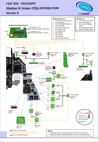
- F16 Block 52 with PSCockpit Main Board + Disp&Gauges: F-16 Distribution File D&G
- F16 Block 52: F-16 Distribution File
- A10C: A-10 Distribution File
HOW TO’s:
- List of all PSCockpit HOW TO’s: http://psfalcon.blogspot.com.es/2015/05/list-of-all-pscockpit-system-how-tos_2.html
PAST RUN POSTS:
- First run post: http://viperpits.org/smf/index.php?topic=7237.0
- Second run post: http://www.viperpits.org/smf/index.php?topic=8679.0
- Third run post: http://www.viperpits.org/smf/index.php?topic=9235.0
- Four run post: http://www.viperpits.org/smf/index.php/topic,9774.0.html
- Fifth run post: http://www.viperpits.org/smf/index.php/topic,10254.0.html
- Sixth run post: http://www.viperpits.org/smf/index.php/topic,10715.msg156116.html#msg156116
- Seventh run post: http://www.viperpits.org/smf/index.php?topic=11042.0
- Eight run post: http://www.viperpits.org/smf/index.php?topic=11294.0
- Nine run post: http://www.viperpits.org/smf/index.php?topic=11629.0
CURRENT DEVELOPED BOARDS:
- Main PCB
- Digital expander for 40 inputs/outputs
- Digital expander 16 inputs/outputs
- Steppers/Other voltage outputs pcb
- 7 segment displays pcb for 6 displays
- Analogue pcb for 4 inputs/1 output
- OLED display (85mm x 40mm), 256x64 for DED
- I2CtoSPI pcb
- Aircore Controller pcb
- Aircore pcb
- Vibration motors pcb
- I/O Enhancement pcb
Quasi complete boards:
- ICP board (deprecated). See ICP Rev1 board
- Caution Panel board
- UHF board
- CMDS board
- ICP Rev1 board
- X40 board for X40 steppers
- TWP board
- TWA board
- PWM board
- ELEC board
- AUDIO1 and AUDIO2 board.
NEW DEVELOPMENTS PENDING:
- A10C UFC board
- A10C CDU board
- Caution Panel Extension board (A10C)
3D PRINTED COMPONENTS
Regards,
Shep
- F16 Block 52: F-16 Distribution File
- A10C: A-10 Distribution File
HOW TO’s:
- List of all PSCockpit HOW TO’s: http://psfalcon.blogspot.com.es/2015/05/list-of-all-pscockpit-system-how-tos_2.html
PAST RUN POSTS:
- First run post: http://viperpits.org/smf/index.php?topic=7237.0
- Second run post: http://www.viperpits.org/smf/index.php?topic=8679.0
- Third run post: http://www.viperpits.org/smf/index.php?topic=9235.0
- Four run post: http://www.viperpits.org/smf/index.php/topic,9774.0.html
- Fifth run post: http://www.viperpits.org/smf/index.php/topic,10254.0.html
- Sixth run post: http://www.viperpits.org/smf/index.php/topic,10715.msg156116.html#msg156116
- Seventh run post: http://www.viperpits.org/smf/index.php?topic=11042.0
- Eight run post: http://www.viperpits.org/smf/index.php?topic=11294.0
- Nine run post: http://www.viperpits.org/smf/index.php?topic=11629.0
- Tenth run post: PSCockpit System 10th Run: Displays & Gauges PCB! (viperpits.org)
- Eleventh run post: PSCockpit and PSCockpit Displays&Gauges Systems 11th Run!!! (viperpits.org)
- Twelfth run post: https://www.viperpits.org/smf/index.php?topic=12568.0
- Thirteenth run post: https://www.viperpits.org/smf/index.php?topic=12768.0
CURRENT DEVELOPED BOARDS:
- Main PCB
- Digital expander for 40 inputs/outputs
- Digital expander 16 inputs/outputs
- Steppers/Other voltage outputs pcb
- 7 segment displays pcb for 6 displays
- Analogue pcb for 4 inputs/1 output
- OLED display (85mm x 40mm), 256x64 for DED
- I2CtoSPI pcb
- Aircore Controller pcb
- Aircore pcb
- Vibration motors pcb
- I/O Enhancement pcb
- X27 pcb for X27 Stepper motor or Aircore motor
- HYD pcb for X27 Stepper motor or Aircore motor
- Indexer lights AOA and NWS pcb
- Left and right Eyebrow lights pcb
- CPD pcbs. More Info
- EHSI pcb. More info
Quasi complete boards:
- ICP board (deprecated). See ICP Rev1 board
- Caution Panel board
- UHF board
- CMDS board
- ICP Rev1 board
- X40 board for X40 steppers
- TWP board
- TWA board
- PWM board
- ELEC board
- AUDIO1 and AUDIO2 board.
NEW DEVELOPMENTS PENDING:
- A10C UFC board
- A10C CDU board
- Caution Panel Extension board (A10C)
3D PRINTED COMPONENTS
- Gear Landing Set. More Info
- Canopy Spider Set. More info
SYSTEM DESCRIPTION
- System description: Link
SOFTWARE:
- Last version Displays&Gauges Software V1.0.3: Link
FIRMWARE:
- Last firmware version Displays&Gauges: Firmware v1.0.1. See Help/Firmware update on your Displays&Gauges software.
QUICK GUIDE:
- Last quick guide version PSCockpit Displays&Gauges v0.
PCBs DISTRIBUTION SHEET:
- F16 Block 52 with PSCockpit Main Board + Disp&Gauges: F-16 Distribution File D&G
ALL POSTS:
- All posts: PS Tools: Displays & Gauges (psfalcon.blogspot.com)
Regards,
Shep
Saturday, May 2, 2015
LIST OF ALL PSCOCKPIT SYSTEM HOW TO’s:
General
PSCockpit PCB system - General overview
HOW TO Poll the I/O expanders
Digital inputs
HOW TO Interface 3 Positions Switches
HOW TO Use Rotary Encoders
HOW to Use the New Encoder Interface Option
HOW TO Encoding/Multiplexing
Digital Outputs
HOW TO Use 7 Segment Displays
HOW TO Use 5x7 Dot Matrix AlphanumericIntelligent Display SLG2016
HOW TO Implement the Magnetic Held Switches
HOW TO Use AIRCORES in PSCockpit System
Steppers
Displays
Analogue inputs
Complete boards
Backlighting Leds PWM board
A10C UFC and CDU Boards (not developed)
Miscellaneous
HOW TO Assign Key Strokes to Different Programs (Launcher)
HOW TO Get Your Tacan Channels Working
HOW TO Use POWER_OFF Bit
HOW TO Assign commands
HOW TO Assign Commands Directly From yourBMS .key File
HOW TO Configure the Marker Beacon
HOW TO use and configure vJoy in PSCockpit
Firmware
HOW TO Upgrade the Main Board firmware
Other software
PS Keys for Falcon
PS UDP Falcon Server for Android 4.0"
Sunday, April 5, 2015
PS Cockpit Software V.0.9.7 Update
The new version V.0.9.7 of the PS Cockpit Software is available for download!!
PS Cockpit Software V.0.9.7 Changelog:
- Added UHF board and CP board self-configuration (IOLayOut)
- Added UHF Frequency and Channel internal values (Airplane Models)
- Added 0x7A and 0x78 addresses for OLED 1.3" (Adafruit OLED)
- Added On-line HOW TOs (General Settings)
- Added Quick Guide v3 (General Settings)
- Check Errors between Airplane Model and IOLayOut implemented (Airplane Models and IOLayOut)
- Added FTIT range value missing
- Corrected the bug of running the program while no Main Board is connected (window hook).
- CMDS functions on low chaffs and flares corrected
- CMDS works on SGL2016 displays as real
- Steppers X27 168 and X40 added. Only for low speed indicators with no different scales. (Airplane Models)
- Adafruit OLED 1.8" implemented (General Settings)
- Run time cycle improved
- Auto poll chip and I/O expander interrupt implemented (USB Timers)
You can download it at: Download
To update the firmware of the Main Board, visit: PS Cockpit Firmware Update
Thanks all for your patient!!!
Regards,
Shep
PS Cockpit System F16 distribution file
You can download the F16 Cockpit Rev.1 distribution file in pdf format at:
http://www.mediafire.com/download/ww3sfnmyhtv1dhz/F16-PSCockpitDistribution.pdf
And the distribution list in excel format at:
http://www.mediafire.com/download/98x5860vpiykbbn/PSCockpitDistREV1.rar
Regards,
Shep
PS Cockpit Firmware Update
The new
firmware V 1.6.0 for the PS Cockpit Main Boards is available for download!!
PS Cockpit
System Firmware V.1.6.0 Changelog:
- Microchip
bootloader for W7&8 64 bits (4th Run Main Boards and later)
- PSCockpit
logo removed from the OLED displays- New RUN modes: Auto Poll and Expanders Interrupt
- Added control for Adafruit OLED 1.3" (SSD1306)
- Added control for steppers X27-168 and X40 double steppers
You can download
the firmware at: Download
Tools for
upgrading the firmware:
-
Users
of the PS Cockpit Main Boards of the 4th Run can update the
firmware in 64bits Windows operating system (These users do not need to update
the firmware by now) with PSFirmUpdtV2-4thRunMainBoards
- Users of the PS Cockpit Main Boards of previous runs can only update the firmware in 32 bits Windows operating systems PSFirmUpdtV1-PreviousMainBoards tool.
Do not try to update the firmware with the
incorrect tool version!!! It will ruin the firmware. If you have any doubt about your Main Board
tool please send me an email.
Regards,
ShepSaturday, April 4, 2015
HOW TO Poll the PS Cockpit Expanders
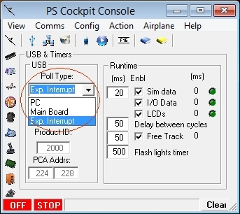
Since PS Cockpit Software V.0.9.7 and firmware version 1.6.0 you can poll the I/O expanders in three different ways:
- PC Mode: In this mode PC is responsible to check all the boards in a given cycle.
- Main Board: In this mode the Main Board will continuously poll the boards and send the values whenever they have changed. It will work better than the previous one.
- Expander Interrupt: In this mode the expanders 16 and 40 I/O expanders their self are responsible to check it one of their inputs have changed and they will ask the Main Board to read the I/O expander.
The selection of the mode can be done in the USB Timers Page of the PS Cockpit Software:
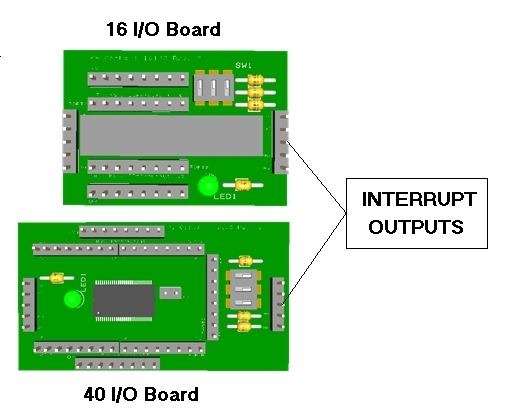
The interrupt inputs of the Main Board are as follows:
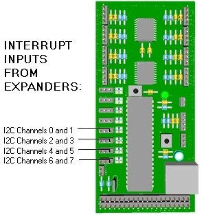
The interrupt outputs of the expanders are the middle pin of the I2C connector:
 As the interrupt outputs of the expanders are open drain active low outputs they need a pull-up resistor connected to 5V+. This can be easily accomplished by adding a 10K resistor to one of the expanders of the I2C daisy chain between the 5V+ pin and the interrupt pin:
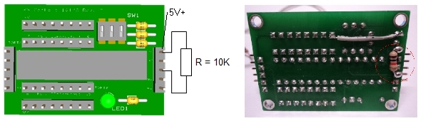
You will need to add this resistor at least to one expander of each I2C channels.
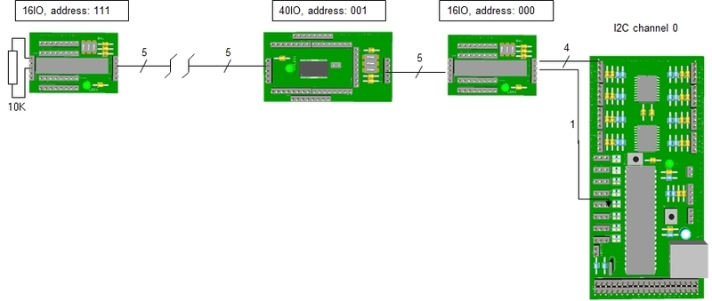
One I2C channel will be look at follows:
- PC Mode: In this mode PC is responsible to check all the boards in a given cycle.
- Main Board: In this mode the Main Board will continuously poll the boards and send the values whenever they have changed. It will work better than the previous one.
- Expander Interrupt: In this mode the expanders 16 and 40 I/O expanders their self are responsible to check it one of their inputs have changed and they will ask the Main Board to read the I/O expander.
The selection of the mode can be done in the USB Timers Page of the PS Cockpit Software:
The interrupt inputs of the Main Board are as follows:
The interrupt outputs of the expanders are the middle pin of the I2C connector:
You will need to add this resistor at least to one expander of each I2C channels.
One I2C channel will be look at follows:
HOW TO Use X27-168 and X40 Steppers
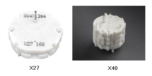
The X27 stepper motor is a miniature stepper developed primarily as an indicator drive for dashboard instrumentation and other indicator equipment. It has a "Lavet" type stepper motor and two step gear train which reduces the rotation by a factor of 180 whereby a full step driving pulse results in a one degree rotation of the pointer shaft.
As the “Lavet” stepper motor needs 6 steps for a full rotation, one full rotation of the pointer shaft will need 1080 steps. Although this value is great for pointer resolution, the PS Cockpit System will not achieve the enough speed to drive the stepper motor for fast dials (i.e. Altimeter, FTIT, Rpm,…). In these cases Aircores motors are recommended.
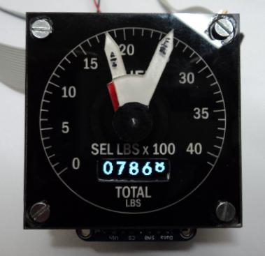
Nevertheless, the X-27 stepper motor can be used in the PS Cockpit System for slow rotating dials (EPU fuel, Cabin Press,…) and the X40, which is basically to X-27 stepper motors in a train with double shaft, can be used in the watch and fuel gauges:
The X27 stepper motors can be connected directly to the 16/40 I/O expanders of the PSCockpit system in 4 consecutive outputs as the maximum current draw of these steppers is 20mA. Of course, the X40 will need 4 more outputs for a total of 8.
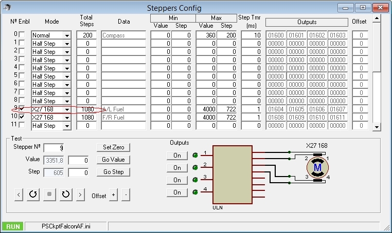
The configuration of the stepper motors in the PS Cockpit software is done in the same way as the unipolar stepper motors. See section “Configuring the stepper motor” in the following post:
PS Cockpit System - How to use steppers
The only difference is that “X27 168” has to be selected in the pull down list:
As the “Lavet” stepper motor needs 6 steps for a full rotation, one full rotation of the pointer shaft will need 1080 steps. Although this value is great for pointer resolution, the PS Cockpit System will not achieve the enough speed to drive the stepper motor for fast dials (i.e. Altimeter, FTIT, Rpm,…). In these cases Aircores motors are recommended.
Nevertheless, the X-27 stepper motor can be used in the PS Cockpit System for slow rotating dials (EPU fuel, Cabin Press,…) and the X40, which is basically to X-27 stepper motors in a train with double shaft, can be used in the watch and fuel gauges:
The X27 stepper motors can be connected directly to the 16/40 I/O expanders of the PSCockpit system in 4 consecutive outputs as the maximum current draw of these steppers is 20mA. Of course, the X40 will need 4 more outputs for a total of 8.
The configuration of the stepper motors in the PS Cockpit software is done in the same way as the unipolar stepper motors. See section “Configuring the stepper motor” in the following post:
PS Cockpit System - How to use steppers
The only difference is that “X27 168” has to be selected in the pull down list:
Edited on April 11th, 2016
-------------------------------------------------------------------------------------------------------------------------
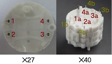
Typical connection for X27 and X40 stepper motors are as follows:
Be aware that X27 and x40 stepper motors do not admit different scales so the gauge you want to drive needs to have the same scale in the full range.
-------------------------------------------------------------------------------------------------------------------------
Regards,
Shep
-------------------------------------------------------------------------------------------------------------------------
Typical connection for X27 and X40 stepper motors are as follows:
Please refer to your stepper motor datasheet for confirmation.
The connection between the stepper motor and the 16 I/O or 40 I/O expanders is straight forward: Select 4 consecutive outputs of the expander and connect them directly to 1 to 4 pins and avoid using outputs between two separate octo-inputs. This means that the four selected outputs have to be between 0-7, 8-15, 16-23, 24-31 or 32-39.
Be aware that X27 and x40 stepper motors do not admit different scales so the gauge you want to drive needs to have the same scale in the full range.
-------------------------------------------------------------------------------------------------------------------------
Regards,
Shep
Subscribe to:
Posts (Atom)