
To give more reality to our pits we can now take advantage of the POWER_OFF bit of the BMS sim (thanks BMS team!!).
You can activate this function by selecting the “Use Power_OFF bit” checkbox in the F-16 Model page under Special I/Os:

- Remove any text in the DED and PFL display
- Activate all the POWER_OFF outputs of the F-16 Model (see picture above)
- More to come….
How to use the Power_OFF outputs in 7 Seg. Displays boards
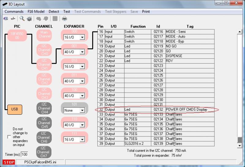
To use this functionality with the 7 seg. displays boards, you will have to define, first, one output in the IOLayout. I have selected one of the 40 I/O board that I have in the CMDS panel to use it with the 7 seg. display board of the CMDS digits:
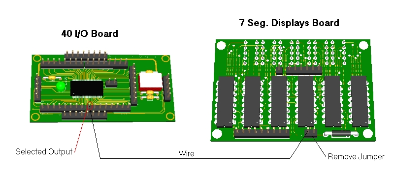
By the way, this PWM input of the 7 Seg. Displays Board can be connected to a PWM output to control the brightness of the displays.
(Added on Dec., 10th)
The Power Off bits have been updated for CMDS and UHF panels.
Now, this is the way PSCockpit works with the Power_Off Bits:
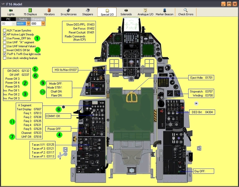
a) The “Use Power_OFF bits” checkbox (number 1), when checked, allows the software to use the Power Off bits (number 2), Inverted Power Off bits (number 3), OFF CMDS (number 5) and OFF UHF (number 6).
b) Power Off outputs (number 2) will be set to HIGH when the sim is in Power Off condition and Inverted Power Off outputs (number 3) will be set to LOW when the sim is in Power Off condition and vice versa when the sim is not in Power Off condition. Some devices will need a HIGH signal and some others may need a LOW signal.
c) The Power Off condition of the sim is an internal signal. In BMS, it comes from the Shared Memory, but, as some other sims (as old versions of BMS), do not have the internal Power OFF value, you can use the function with the Power Off switch of the Elec panel (number 4). This switch must be HIGH when Power Off condition.
d) There are specific Power OFF bits for the CMDS (number 5) and UHF panels (number 6) because some others conditions have been added as below explanations.
e) Off CMDS output (number 5) will be set to HIGH (display OFF) when one of the following inputs/signal are HIGH:
- In BMS: CMDS Off (from BMS Share Memory)
- In Falcon AF: Selector Mode OFF (number 9). Also in this sim, the rest of the inputs (number 10) are used for CMDS displays
- “Invert CMDS Off Bit” checkbox (number 12), when checked, inverts the output Off CMDS.
f) Off UHF output (number 6) will be set to HIGH (display OFF) when one of the following inputs/signals are HIGH:
- Power Off (from BMS shared memory)
- UHF Selector Mode OFF (number 7)
- Selector COMM1 Off (number 8)
- All other values for UHF (number 11) are used only to use internal frequency. It is used in other sims where the frequency is not available.
Regards,
Shep
No comments:
Post a Comment