

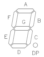
PS Cockpit System PCB for 7 segment displays is able to drive up to (6) Avago 7 segment displays. The Avago 7 segment displays are not supplied with the PCB so you can use the ones you like (Kingbright, Lite-On, …) . Just carefully connect the pins of the segments to the PCB. The 7 segments displays have to be common cathode and 5VDC if you want them to be sourced by the PS Cockpit System.
The 7 segment displays PCB has three different headers:
- Expander header: used to connect the PCB with the desired expander. It has the 5VDC supply, ground, one signal for each display and the reset pin for all the displays.
- Common cathode header: used to be connected to a dimmer system. If no dimmer solution is going to be used then a jumper must be plugged in.
- Dot header: if you have a number with a decimal dot, you can select where do you want the dot to be positioned placing a jumper between the first pin and pin of the desired display.
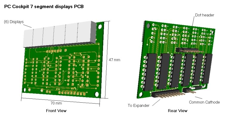
The board has a total length of 70 mm and a total height of 47 mm and it is designed to plug directly Avago 7.6 mm models A803 (yellow) or A903 (green) and has the connectors and the chips on the back side to mount the PBC directly onto the panel.
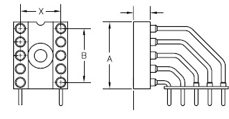
If there is any device blocking this type of mounting you can use the Andon socket for the Avago displays so the PCB will mounted tangent to the panel:
Is it too expensive for you? Or, do you want to use other smaller or different brand displays? Then you can always glue the displays on the border of the PCB and wiring the pins to the PCB
 :
: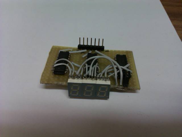
There is no need to use the 6 displays on the board, you can choose by software 3, 4, 5 and 6 displays.
Ok. Now I have 3 displays I’m going to use as the rpm indicator of the falcon sim. Let’s first connect the PCB to the desired expander, of course the nearest one I have in my cockpit. This is going to be the 001 expander of the I2C Channel 0:
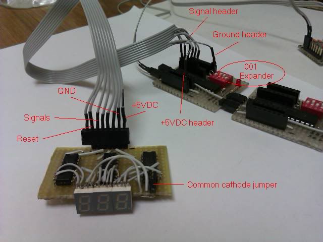
Carefully connect the following wires:
- +5VDC to the +5VDC header of the expander
- GND to the GND header of the expander
- Signals and reset to the signals header of the expander. Depending on how many displays you want to drive you have to connect 4, 5, 6 or 7 wires. Remember, one wire for each display plus one for the reset. I have selected pins number 3, 4 5 and 6 of the 16 IO expander.
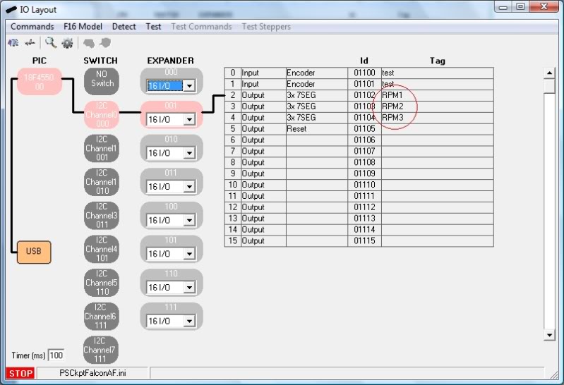
Let’s configure the software: Select IO Layout, I2C Channel 0 and expander 001 so we have the list of IOs of that expander. Select “Output” on the first dropdown list and “3x7SEG” on the second dropdown list.

The software automatically will fill the following lines according to its needs when you accept and you can fill the tag field as desired:
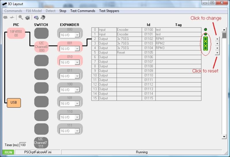
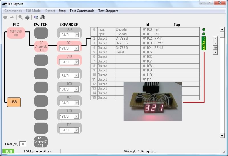
Time for testing: Click on the Test command, you will see a 7 segment display icon with the number you have on the display. Click on the “+” command on the right and the number of that display will change accordingly. Click on the “+” command of the reset pin and all the displays will go to 0:
 .
. Just one final step and we are done: we have to tell the software that we want this display to be the rpm of the sim. To do this, go to the F16 Model screen and select 7Seg Display where you will see all the data of the F16 that can be showed in this type of displays:
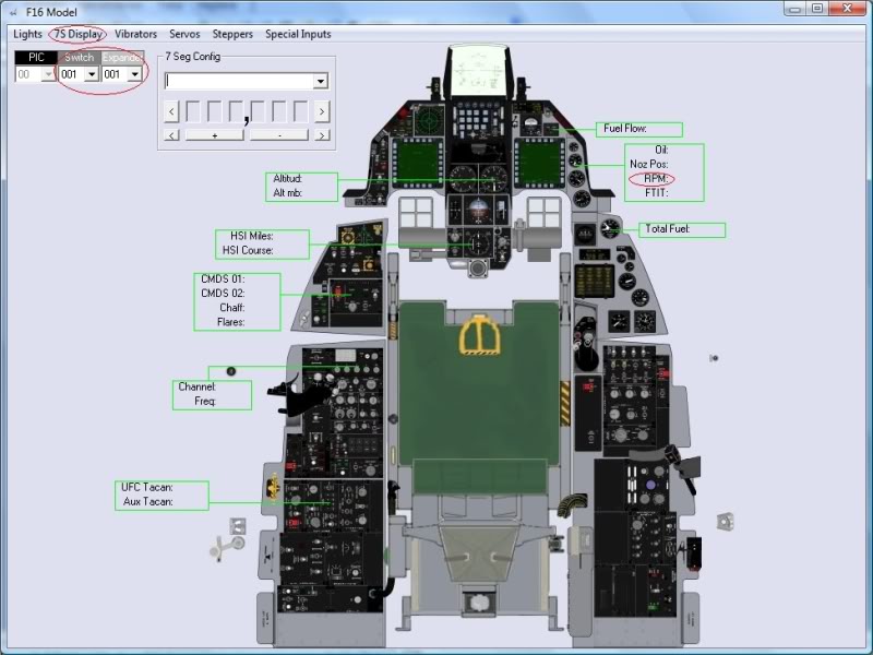
Now select the switch and the expander and click on RPM a dropdown list will appear with the 7 Segment Displays configured on that expander, in this case, the only one we have configured called RPM1. The first pin of this display will appear near the tag RPM.
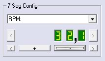
Now we have to configure the format of the number. In the “7 Seg Config” panel select RPM on the dropdown list and will appear the number of digits you have in your display, 3 in this case.

Now we can format the number with the following tools:
- Moving the 3 numbers to the right or to the left.
- Adding/removing digits.
- Moving the decimal point to the right or to the left.
I’m going to use the RMP with one decimal so I adjust the format accordingly:
Now I run the PS Cockpit software in normal mode and run our favourite sim. I have used FalconAF for this example:
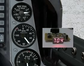
Sorry I don’t have the decimal point option in this PCB
 .
.Edited on Apri 11th, 2016
--------------------------------------------------------------------------------------------------------------------------
You can also use one 6 digits 7 segment display pcb to show to different magnitudes. To do this, follow this procedure:
1. Select the same address of the 7 segment display in the Airplane model:
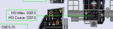
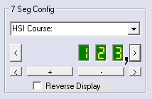
2. Select the first magnitude in the dropdown list and configure the digits in such way that the magnitude will use the 123 digits:
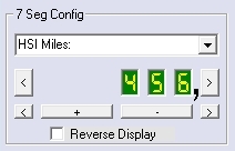
3. Select the second magnitude in the dropdown list and configure the digits in such way that the magnitude will use the 456 digits:
--------------------------------------------------------------------------------------------------------------------------
Regards,
Shep
No comments:
Post a Comment