
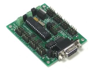
To use the servos of the PS Cockpit System Main PCB you need first to supply power to the servo power supply header. Usually the servos are powered with 6VDC but you can use 5VDC from the power supply of your cockpit (i.e. PC power supply).
As the power is supplied to all servos they have to be of the same voltage.
Be aware of the type of your servo: Most of the servos can move up to 180º of rotation but they can be damaged when commanded past their mechanical limitations. PS Cockpit system limits the movement of the servo up to 170º for conservative purposes. Some servos have only a 90º of motion. I don’t recommend using these types of servos as the precision of the gauge we are trying to drive will be lower.
As the range of the servo will be limited to 170º you will need a gear system to drive gauges that past this 170º movement. For better resolution choose a gear system with many teeth as possible and with a relation that better fits the 170º to the range of the gauge.
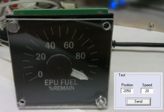
For this example I have chosen the EPU Fuel gauge with a Cyclone CY130011 which gives us a torque of 0.8 Kg/cm at 4.8VDC. As the EPU Fuel gauge has a total movement of approximately 240º I have chosen a gear system of 32/10 so I will need 90º of rotation of the servo for 288º of the gauge (90 *32/10=288º).
I have connected it to the port 6 of the servo header.
The configuration of the servo is done in the F-16 Model page selecting “Servos/PWM”. In the left frame you have to set the following parameters:
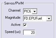
- Channel: The output you have connected the servo. The syntax used is a number for the Lynxmotion SSC-32 channel
- Magnitude: The magnitude of the sim which is going to be tied to the servo. “FD.EPUFuel” for my example.
- Active: Select the checkbox if you want the servo to be active.
- Speed: The speed you want the servo to be moved from one position to another. A lower value means a more smoothness movement of the servo but also a less synchronization of the reading with the sim. The speed parameter is very useful to reduce the noise of the servo and for avoiding heavy strokes on it so you should find a value of each gauge to accomplish smoothness with accuracy.
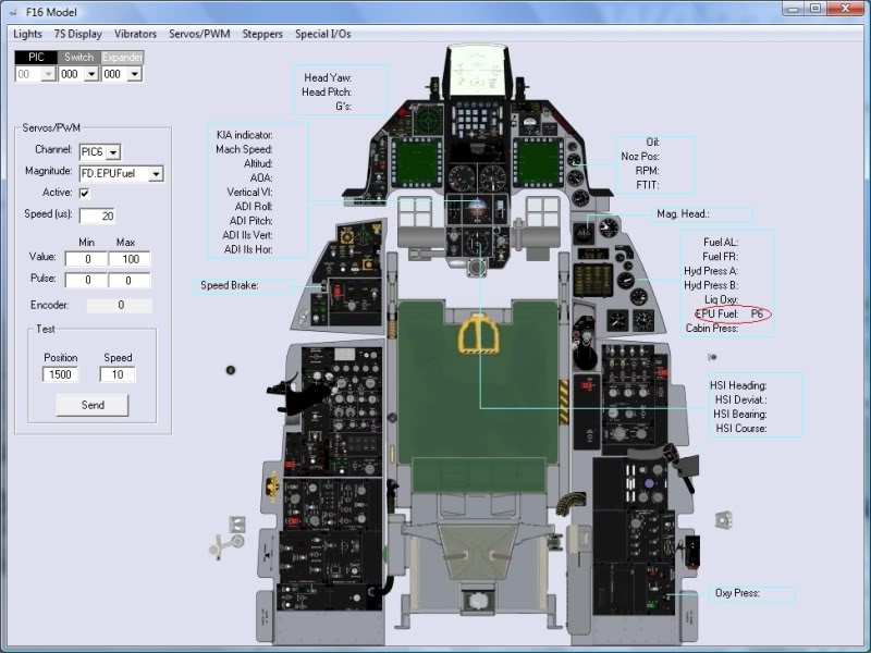
Once the data has been set you will see the F-16 model screen updated:
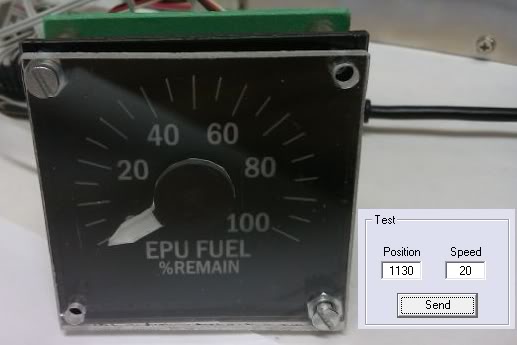
Now we are going to set the servo movement range and make the relationship with the magnitude. The RC servos in the PS Cockpit System have a resolution of 1500 units from 750 to 2250. These figures represent the wave length in ms multiplied by 1000 which are going to be sent to the servo each 20 ms. (1500 = 1.5 ms).
The 750-2250 range limits the movement of the servo up to 170º for conservative purposes. For servos with only a 90º of motion you have to adjust the pulse from 900 to 2100.
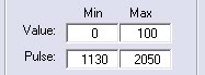
Using the Test frame and taking in account the above considerations we have to move the servo to the 0 and the 100 positions of the gauge scale and save the values:
Now we have the values of the position of the servo we can set the parameters of the magnitude:
This servo is driven clockwise, for counter clockwise operation mode, just change the value between them, having 100 in the Min value and 0 in the Max value. The software will do the rest for you.

For gauges that have no linear scales like FTIT, RPM and ASI, see Step 7: Adding intermediate scales to your gauge in the following post: HOW to Use Aircores
Best regards,
Shep
Shep, would you recommend this or the adafruit to drive all servo gauges in the F16? I've started building again, so I'll be buying more parts from you
ReplyDeleteThanks, Jim
Hi Jim,
ReplyDeleteThe SSC-32 has more configuration options to drive servos which make them run smoother: speed, time to reach the value and two different voltages for servos. The drawback is that it needs a serial RS232 output in your computer.
The Adafruit Servo board is connected to the I2C channel.
Regards,
Shep
Hey Shep,
ReplyDeletewhat kind of gear system do you use? Can you give me a link?
Regards
MadDoc