Saturday, January 4, 2020

HOW TO Configure the AUDIO1&2 Panel


For AUDIO1&2 pcb description, options and how to configure the expander address, see PSCockpit Quick Guide V.5 – AUDIO1&2 PCB. You can access the Quick Guide from Help/Quick Guide menu in the PSCockpit software.


The AUDIO1&2 pcb must be configured either the digital expander and analogue expanders.

AUDIO1&2 Digital Expander

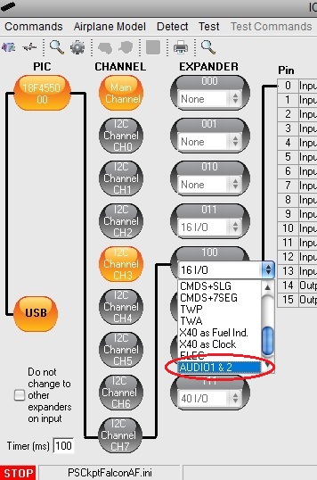
To configure the PSCockpit AUDIO1&2 panel select the correct option from the Expander pull down list in the IOLayout page of the PS Cockpit Software at the correct I2C channel:


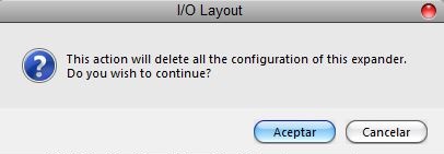
In case of there is some data already in the selected expander, the software will prompt you for continue:

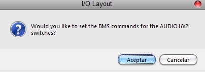
The software will also prompt you to add the standard BMS commands for the AUDIO1&2:

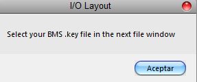
If you accept, the software will prompt you to search for your BMS .key file, typically in ..\Falcon BMS vX.X\User\Config folder, and will automatically search for the keystrokes you have set in your .key file for the AUDIO1&2:

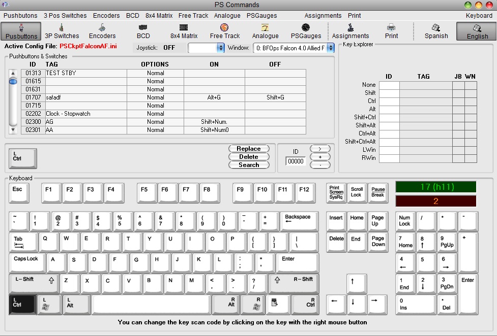
If any of the commands hasn't been set you will see a warning indicating how many commands haven't been set and the Commands page of the PSCockpit software will appear:
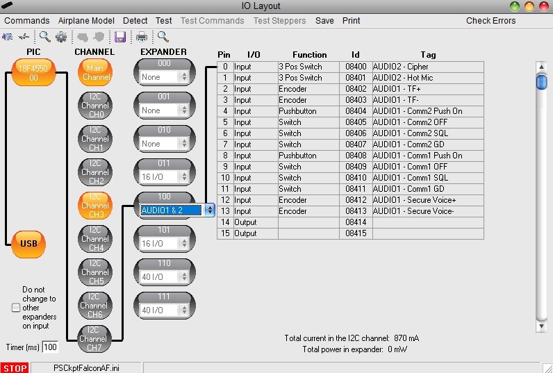
Once the AUDIO1&2 panel is already configured you can modify the list of inputs/outputs as desire as well as the free I/O of the expander:


Be aware that once the configuration is saved, whenever you enter the IOLayout Page you won’t see “AUDIO1&2” label on the expander anymore but the “16 I/O” label.

AUDIO1&2 Analogue Expander

In the same way as the digital expander, to configure the PSCockpit AUDIO1&2 panel for analogue inputs, select the correct option from the Expander pull down list in the IOLayout page of the PS Cockpit Software at the correct I2C channel in the Main Channel:
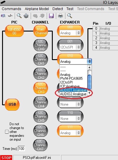

You need to repeat the process for AUDIO1 analogue inputs and AUDIO2 analogue inputs in different analogue expander addresses.

In case of there is some data already in the selected expander, the software will prompt you for continue:


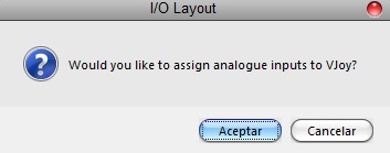
The software will prompt you to assign the analogue inputs to VJoy:


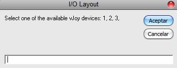
If you accept, the software will prompt you to select one of the free available vJoy devices:


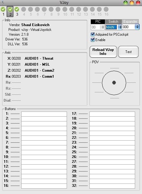
The VJoy page will appear. You can select the devices you have previously selected to see the configuration:

For more information about configuring vJoy devices, see:

Once the analogue inputs of the AUDIO1 panel is already configured you can modify the list of analogue inputs as desire:


Be aware that once the configuration is saved, whenever you enter the IOLayout Page you won’t see “AUDIO1 Analogue” label on the expander anymore but the “Analogue” label.

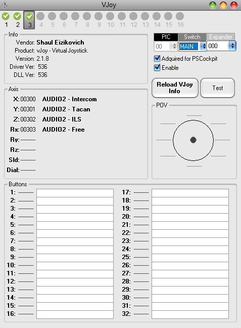
For AUDIO2 analogue inputs you need to repeat the process of the analogue input configuration and the vJoy page and IOLayout should appear like these:

For more information about configuring vJoy devices, see:
https://psfalcon.blogspot.com/2020/01/how-to-use-and-configure-vjoy-in.html
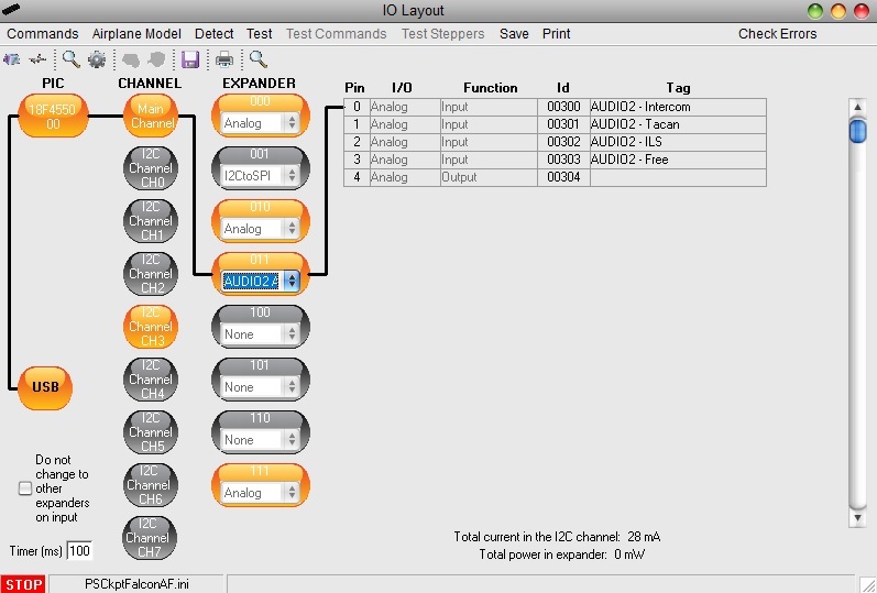


Be aware that once the configuration is saved, whenever you enter the IOLayout Page you won’t see “AUDIO2 Analogue” label on the expander anymore but the “Analogue” label.

Regards,
Shep

HOW TO use and Configure vJoy in PSCockpit


To use vJoy application for PSCockpit you must install the vJoy drivers in your computer. Please refer to http://vjoystick.sourceforge.net/site/ on how to download and install the vJoy device driver.

To use vJoy with PSCockpit you need PSCockpit Software v.1.0.3 or higher and firmware version v.1.0.3 or higher.

To check these versions, click on Help/About menu of the PSCockpit Software.

Refer to this page for latest updates:

https://psfalcon.blogspot.com/2015/05/pscockpit-system-up-to-date-software.html

Once you have installed the vJoy driver you must configure your VJoy devices. Typically, you will need to configure 3 devices for PSCockpit analogue expanders:

-      ICP Rev.1 Analogue
-      AUDIO1 Analogue
-      AUDIO2 Analogue

To do this, open the “Configure vJoy” application and configure one device following the next procedure:

1. Select the device number
2. Select the desired number of axes. In PSCockpit you will need as much as five axes per digital expander.
3. Select the number of buttons. You can select maximum 32 pushbuttons to use them in PSCockpit.
4. Select “Enable vJoy”
5. Click on “Apply”. Be aware that vJoy will ask you to restart your computer, so you might want to configure also device 2 and 3.


Once you have configured your vJoy devices, you can click on vJoy icon of the PSCockpit main screen to configure the analogue and digital inputs to be used with it:


You will be warned about the faults encountered (i.e. wrong vJoy version), otherwise, if everything is correct, the vJoy configuration page will appear, 


You can configure your PSCockpit analogue and digital inputs by following this procedure:

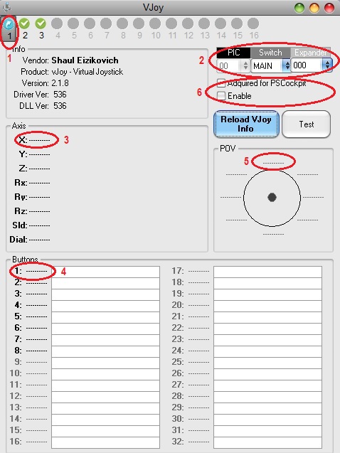
1. Select the vJoy device by clicking on the device number tab. They can appear in different states:

- Shaded icon: vJoy device is not available. You need to configure in “Configure vJoy” application. Please refer at the top of this document.
- Blue arrow icon: vJoy device is configured and free to be acquired for any application.
- Red cross icon: vJoy is configured and has been acquired for other application than PSCockpit.
- Green check icon: vJoy is configured and acquired for PSCockpit.

2. Select the I2C channel and expander you will use to assign inputs on vJoy.
3. Click on one axis label to display the dropdown list where to select the desire input. Available axis will be shown in bold, unavailable axis will be shown in grey.
4. Click on one button label to display the dropdown list where to select the desire input. Available buttons will be shown in bold, unavailable buttons will be shown in grey.
5. Click on one POV label to display the dropdown list where to select the desire input. Available POVs will be shown in bold, unavailable POVs will be shown in grey.
6. Check “Acquired for PSCockpit” and “Enable”. The device number icon should change to Green check icon indicating that this vJoy device has been acquired for PSCockpit.

Use “Reload vJoy Info” button to refresh any change you do on vJoy Config application.

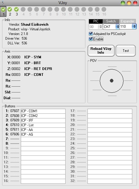
Once configured you will see the vJoy page, i.e. for the ICP panel:


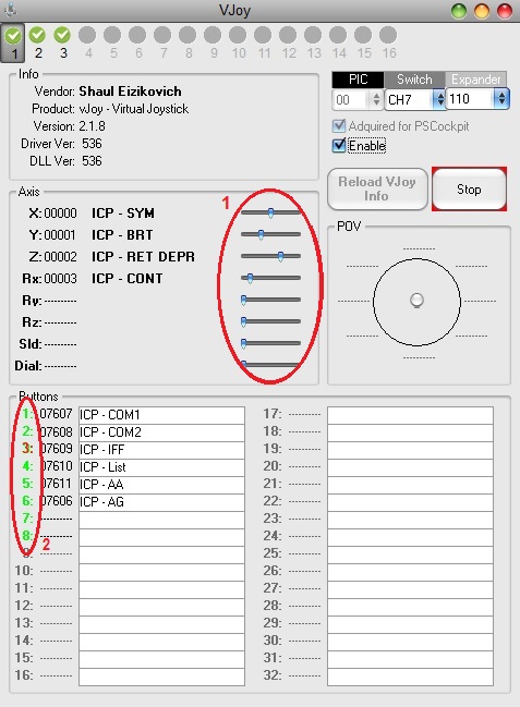
You can now enter in Test mode by clicking on TEST button. The vJoy page will appear as this:


You will be able to test the interaction with vJoy by moving the Axis sliders (1) and clicking on the button number (2). Numbers in green shows the available buttons and numbers in red shows the button pressed.

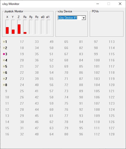
The interaction with vJoy can be seen by opening the “vJoy Monitor” application of vJoy:


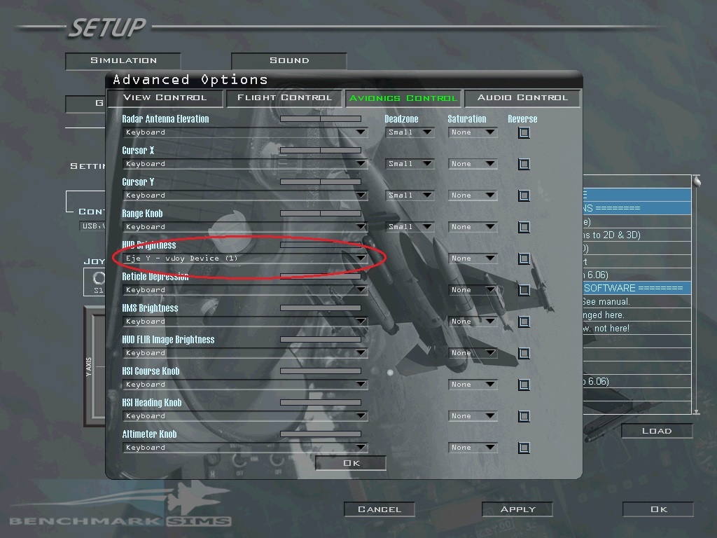
To finish the configuration of the vJoy device in your favourite sim, select the desire axis or DX button for a selected function. In case of BMS, go to Setup/Controllers/Advanced/Avionics Control:


Regards,

Shep

HOW TO Configure the ELEC Panel


For ELEC pcb description, options and how to configure the expander address, see PSCockpit Quick Guide V.5 – ELEC PCB. You can access the Quick Guide from Help/Quick Guide menu in the PSCockpit software.

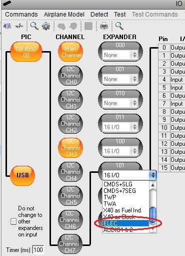
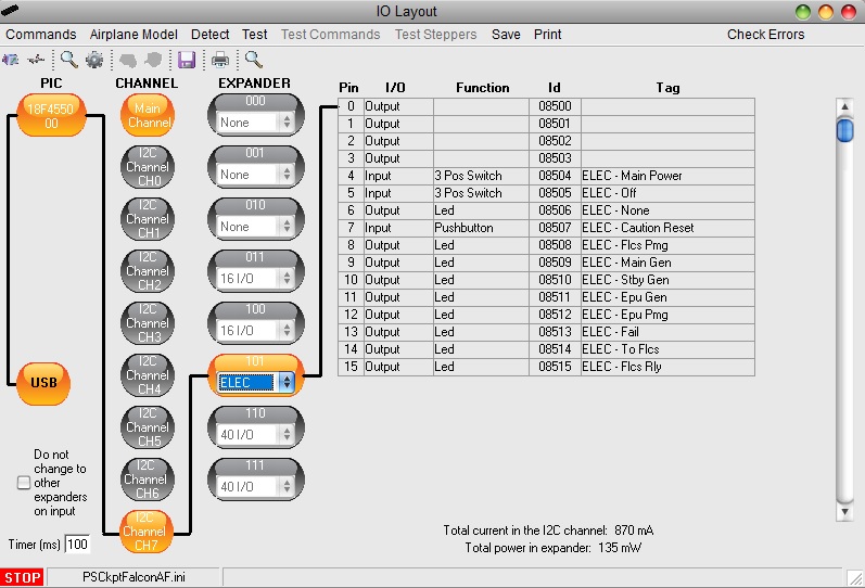
To configure the PSCockpit ELEC panel select the correct option from the Expander pull down list in the IOLayout page of the PS Cockpit Software at the correct I2C channel:


In case of there is some data already in the selected expander, the software will prompt you for continue:


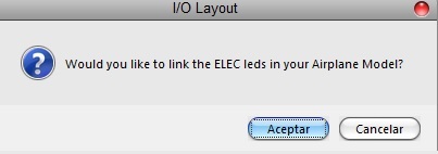
The software will prompt you to setup the ELEC leds in our Airplane model:


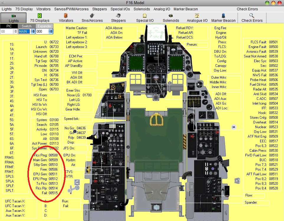
If you accept, the Airplane page will show up with the leds already assigned:


The software will also prompt you to add the standard BMS commands for the ELEC:


If you accept, the software will prompt you to search for your BMS .key file, typically in ..\Falcon BMS vX.X\User\Config folder, and will automatically search for the keystrokes you have set in your .key file for the ELEC panel:

If any of the commands hasn't been set you will see a warning indicating how many commands haven't been set and the Commands page of the PSCockpit software will appear:


Once the ELEC panel is already configured you can modify the list of inputs/outputs as desire as well as the free I/O of the expander:


Be aware that once the configuration is saved, whenever you enter the IOLayout Page you won’t see “ELEC” label on the expander anymore but the “16 I/O” label.


Regards,
Shep

Friday, January 3, 2020

HOW TO Configure the X40 pcb


For X40 pcb description, options and how to configure the expander address, see PSCockpit Quick Guide V.5 – X40 PCB. You can access the Quick Guide from Help/Quick Guide menu in the PSCockpit software.

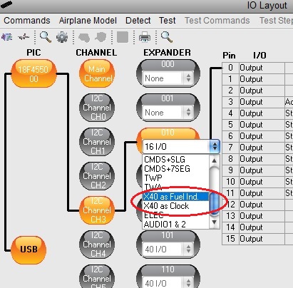
To configure the PSCockpit X40 pcb, select the correct option from the Expander pull down list in the IOLayout page of the PS Cockpit Software at the correct I2C channel, depending if you want to configure the board as Fuel Indicator or as Clock:


In case of there is some data already in the selected expander, the software will prompt you for continue:


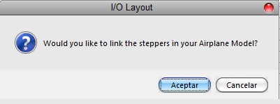
The software will prompt you to setup the X40 steppers in your Airplane model:


If you accept, the Airplane page will show up with the steppers already assigned and you will be warned to set the zero, minimum and maximum values of the steppers:


X40 PCB AS FUEL INDICATOR:


In case of Fuel Indicator, the software will prompt you to configure the Adafruit display:


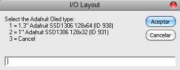
If you accept you will be prompted to select the type of Adafruit display:


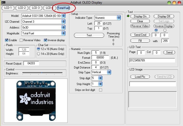
The Adafruit Display Page will show up with the configuration. Click on “Total Fuel” tab to review it:


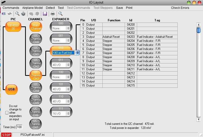
The configuration of the X40 pcb for Total Fuel Indicator is now completed and the IOLayout should appear like this:


You can now modify the list of inputs/outputs as desire as well as the free I/O of the expander.
Be aware that once the configuration is saved, whenever you enter the IOLayout Page you won’t see “X40 as Fuel Ind” label on the expander anymore but the “16 I/O” label.

X40 PCB AS FUEL INDICATOR:
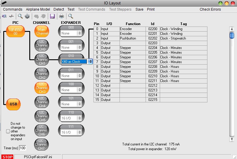
The configuration of the X40 pcb for Clock is now completed and the IOLayout should appear like this:


You can now modify the list of inputs/outputs as desire as well as the free I/O of the expander.
Be aware that once the configuration is saved, whenever you enter the IOLayout Page you won’t see “X40 as Clock” label on the expander anymore but the “16 I/O” label.

To configure the stepper motors, see:

Regards,
Shep


Thursday, January 2, 2020

HOW TO Configure the TWP & TWA Panels


For TWP and TWA pcb descriptions, options and how to configure the expander address, see PSCockpit Quick Guide V.5 – TWP PCB page and TWA PCB page. You can access the Quick Guide from Help/Quick Guide menu in the PSCockpit software.

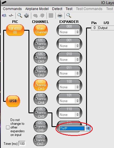
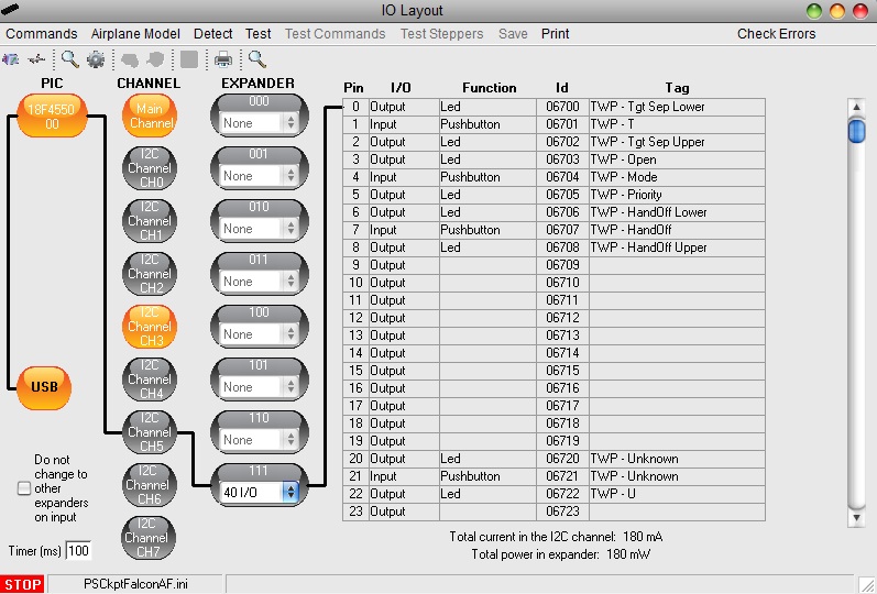
To configure the PSCockpit TWP or TWA panel select the correct option from the Expander pull down list in the IOLayout page of the PS Cockpit Software at the correct I2C channel:


In case of there is some data already in the selected expander, the software will prompt you for continue:


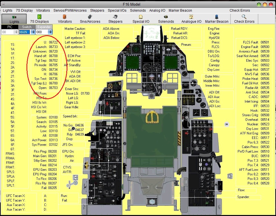
The software will prompt you to setup the TWP leds in our Airplane model:


If you accept, the Airplane page will show up with the leds already assigned:


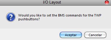
The software will also prompt you to add the standard BMS commands for the CMDS:


If you accept, the software will prompt you to search for your BMS .key file, typically in ..\Falcon BMS vX.X\User\Config folder, and will automatically search for the keystrokes you have set in your .key file for the TWP:


If any of the commands hasn't been set you will see a warning indicating how many commands haven't been set and the Commands page of the PSCockpit software will appear:


Once the TWP panel is already configured you can modify the list of inputs/outputs as desire as well as the free I/O of the expander:

Be aware that once the configuration is saved, whenever you enter the IOLayout Page you won’t see “TWP” label on the expander anymore but the “40 I/O” label.
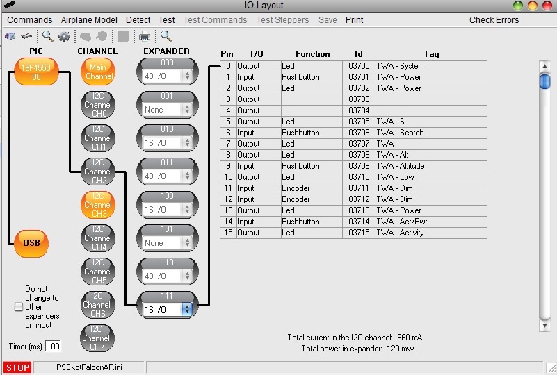
The configuring process for the TWA is exactly the same and the IOLayout page should be like this:


Be aware that once the configuration is saved, whenever you enter the IOLayout Page you won’t see “TWA” label on the expander anymore but the “16 I/O” label.

Regards,
Shep
PSCockpit 9th Run

Time to launch a new run of the PSCockpit System!!

Attending several requests from you, I’m launching the 9th Run of PSCockpit, but, due to the lack of free time, there won’t be any new board this year.

I’m still working on the PSCockpit Software update to correct some minor issues:
- Implementing VJoy for analogue inputs
- Updating software for BMS 4.34 U1
- Updating software for F16 DCS.
This update version will be launched on week 2 of year 2020.

Thanks everybody for the patient you´ve had this year and have a Merry Christmas

System Description
- One stop hardware and software for cockpit systems. Once the cockpit is connected you can configure the software individually for each sim.
- Easy configuration and setup for people without electronic knowledge.
- Avoid excessive wiring runs along the cockpit.

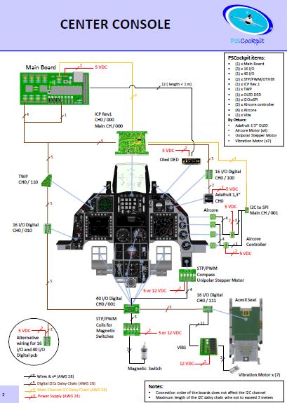
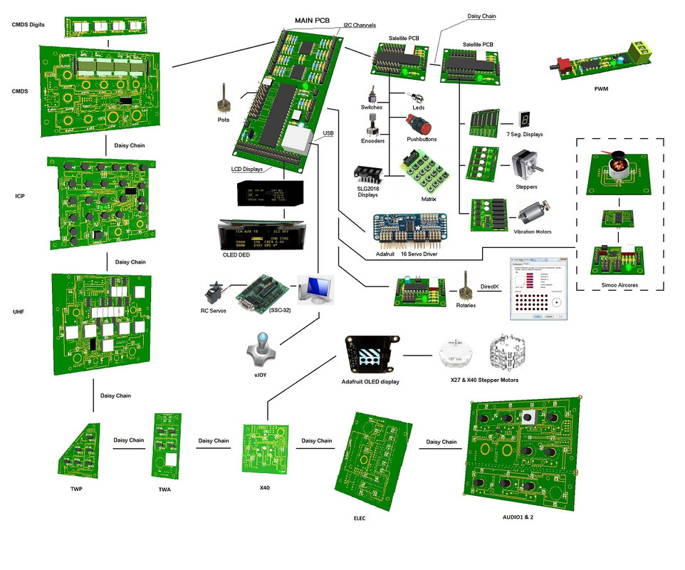
The system uses small satellite PCB’s that can be distributed along the cockpit. The communication between these satellite PCB’s and the Main PCB is done with only 2 wires (I2C protocol) plus the power cables. These wires can be connected in daisy chain. The idea is to wire each of the cockpit panels to only one satellite PCB. See F16 distribution example:


You can download at: http://psfalcon.blogspot.com.es/2016/12/ps-cockpit-system-f16-distribution-file.html

Supported devices
-   Digital inputs: Pushbuttons, 2 position switches, 3 position switches, digital encoders, BCD encoding (8 to 3, 16 to 4, 32 to 5) and 8x4 matrixes
-   Digital outputs and leds
-   Analogue inputs and outputs
-   Vibration motors
-   Aircores motors
-   Stepper motors: Unipolar, X27 and X40
-   RC Servomotors
-   Segment Displays: 7 segments and SLG2016
-   LCD displays: SSD1322 Graphic display 264x64, KS0108 Graphic display 128 x 64, KS0108B Text display 20x4, SSD1306 Adafruit 128x64 (ID938 and ID931)


More information, downloads and guides at http://psfalcon.blogspot.com.es/2015/05/pscockpit-system-up-to-date-software.html

Prices
The prices of the PCB’s already mounted and tested are the following:
- Main PCB: 60 €
- Digital expander for 40 inputs/outputs: 33 €
- Digital expander 16 inputs/outputs: 10 €
- Steppers/Other voltage outputs pcb: 28 €
- 7 segment displays pcb for 6 displays: 18 €
- Analogue pcb for 4 inputs/ 1 output: 20 €
- Yellow OLED display (85mm x 40mm), 256x64 for DED or PFL: 55 €
- I2CtoSPI pcb: 25€
- Aircore Controller pcb: 24€
- Aircore pcb: 15€
- Vibration motors pcb: 38€
- I/O Enhancement pcb: 6,5€
- Caution Panel board: 40€
- UHF board: 90€
- ICP pcb Rev 1: 90€
- CMDS board (with 2 rotary switches 30ΒΊ & 45ΒΊ, no toggles, no displays): 80€
- CMDS options:
   - Miniature toggles 6 mm diam. (1 with locking lever): 40€
   - SGL2016 displays: 35€ (each)
   - HDLG-1414 displays: 20€ (each)
   - 7 segment displays pcb with 8 displays: 35€
- TWP board: 40€
- TWA board: 20€
- X40 stepper board: 20€
- PWM board: 20€
- ELEC board: 50€
- AUDIO1 & AUDIO2 board: 100€

- Shipment: 15€ / 25€ depending on the total weight order

Time Line:
- Orders will be accepted until Jan. 19th. 2020
- Only direct bank transfers for payments. Sorry for the inconvenience.
- Delivery: Starting March 2020

Regards,
Shep

Monday, March 4, 2019

PWM, ELEC and AUDIO Boards

Let me share with you the last three beauties of the PSCockpit system:

PWM


ELEC


AUDIO:


Hopefully, I would be able to begin shipping the boards next week. Please be patient waiting for your shipping turn.

Regards,
Shep
Wednesday, December 12, 2018

PSCockpit System 8th Run!!!

Sorry, guys, I forgot to announce the 8th Run here:

System Description
- One stop hardware and software for cockpit systems. Once the cockpit is connected you can configure the software individually for each sim.
- Easy configuration and setup for people without electronic knowledge.
- Avoid excessive wiring runs along the cockpit.

The system uses small satellite PCB’s that can be distributed along the cockpit. The communication between these satellite PCB’s and the Main PCB is done with only 2 wires (I2C protocol) plus the power cables. These wires can be connected in daisy chain. The idea is to wire each of the cockpit panels to only one satellite PCB. See F16 distribution example:


You can download at: http://psfalcon.blogspot.com.es/2016/12/ps-cockpit-system-f16-distribution-file.html

Supported devices
-   Digital inputs: Pushbuttons, 2 position switches, 3 position switches, digital encoders, BCD encoding (8 to 3, 16 to 4, 32 to 5) and 8x4 matrixes
-   Digital outputs and leds
-   Analogue inputs and outputs
-   Vibration motors
-   Aircores motors
-   Stepper motors: Unipolar, X27 and X40
-   RC Servomotors
-   Segment Displays: 7 segments and SLG2016
-   LCD displays: SSD1322 Graphic display 264x64, KS0108 Graphic display 128 x 64, KS0108B Text display 20x4, SSD1306 Adafruit 128x64 (ID938 and ID931)


More information, downloads and guides at http://psfalcon.blogspot.com.es/2015/05/pscockpit-system-up-to-date-software.html

Prices
The prices of the PCB’s already mounted and tested are the following:
- Main PCB: 60 €
- Digital expander for 40 inputs/outputs: 33 €
- Digital expander 16 inputs/outputs: 10 €
- Steppers/Other voltage outputs pcb: 28 €
- 7 segment displays pcb for 6 displays: 18 €
- Analogue pcb for 4 inputs/ 1 output: 20 €
- Yellow OLED display (85mm x 40mm), 256x64 for DED or PFL: 55 €
- I2CtoSPI pcb: 25€
- Aircore Controller pcb: 24€
- Aircore pcb: 15€
- Vibration motors pcb: 38€
- I/O Enhancement pcb: 6,5€
- Caution Panel board: 40€
- UHF board: 90€
- ICP pcb Rev 1: 90€
- CMDS board (with 2 rotary switches 30ΒΊ & 45ΒΊ, no toggles, no displays): 80€
- CMDS options:
   - Miniature toggles 6 mm diam. (1 with locking lever): 40€
   - SGL2016 displays: 35€ (each)
   - HDLG-1414 displays: 20€ (each)
   - 7 segment displays pcb with 8 displays: 35€
- TWP board: 40€
- TWA board: 20€
- X40 stepper board: 20€
- Backlighting Leds PWM board: 20€
- ELEC board: 50€
- AUDIO1 & AUDIO2 board: 100€

- Shipment: 15€ / 25€ depending on the total weight order

Time Line:
- Orders will be accepted until Dec. 17th.
- Only direct bank transfers for payments. Sorry for the inconvenience.
- Delivery: Starting February 2019

Regards,
Shep
Monday, December 10, 2018

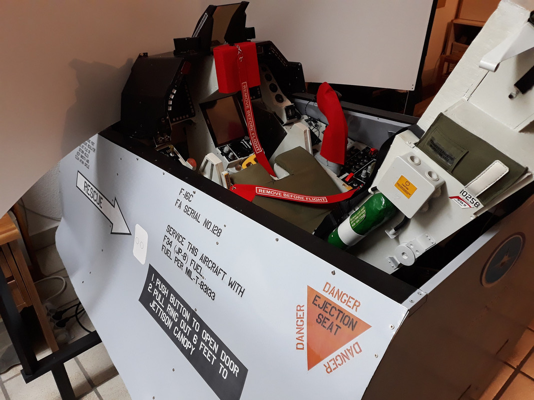
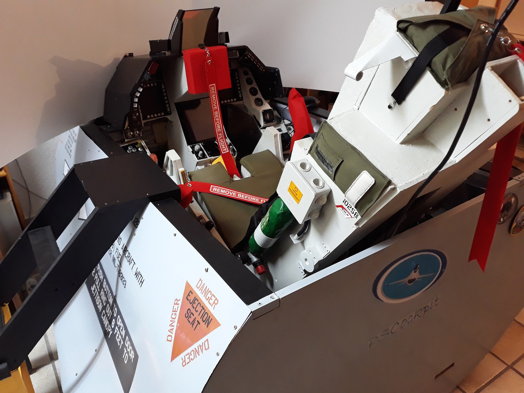
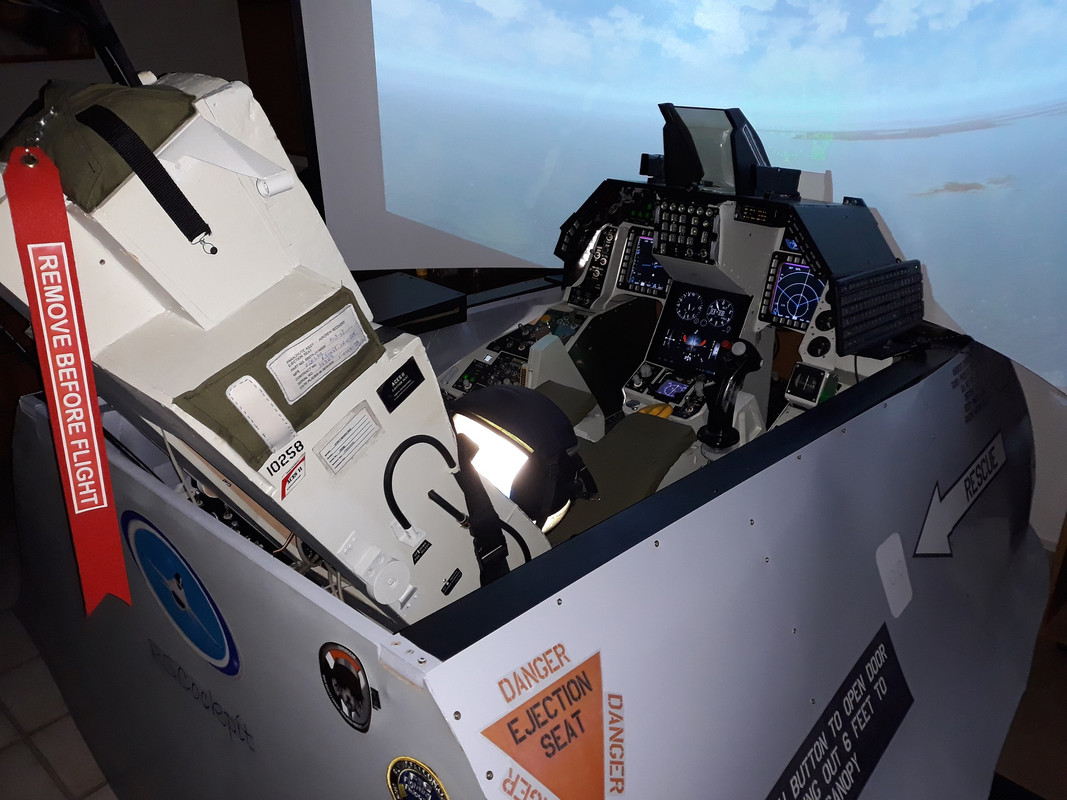
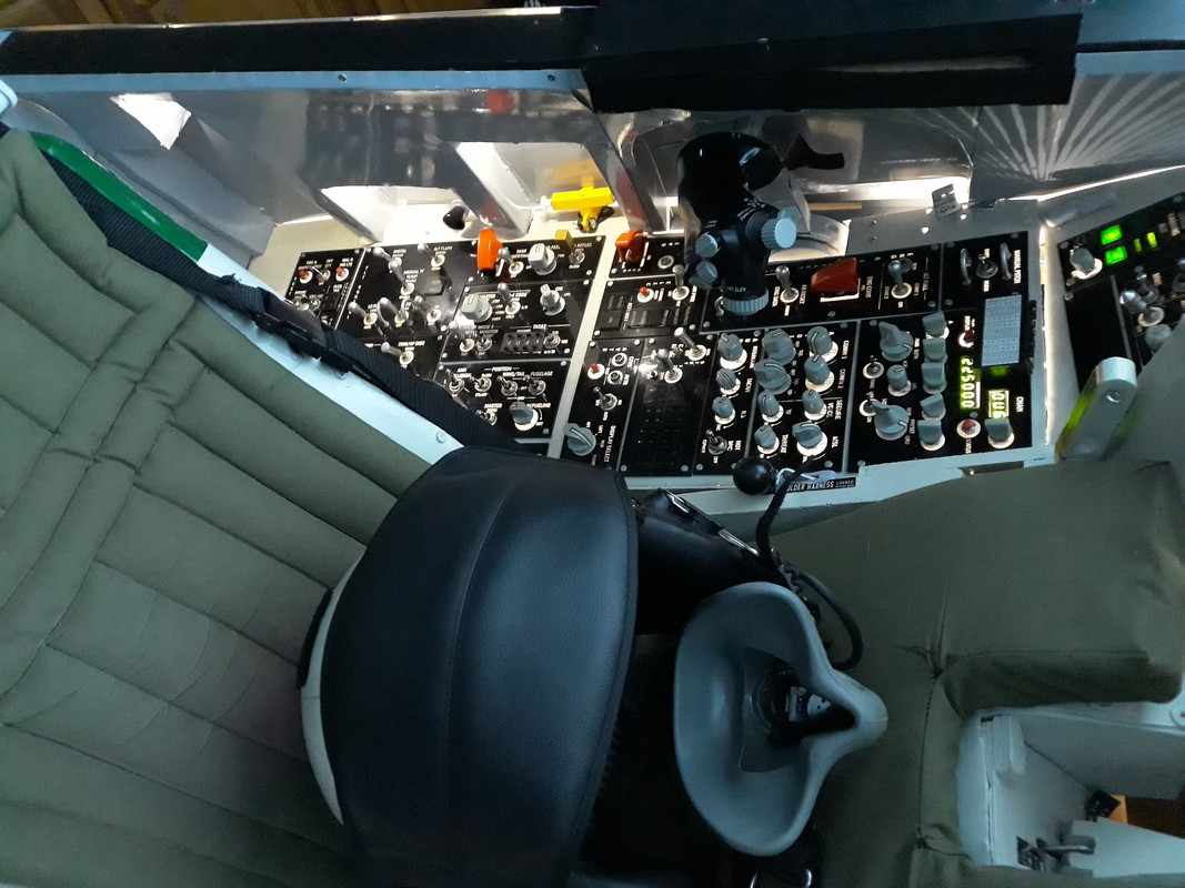
Shep´s cockpit ready for shipment!

After many years of cockpit building, I finally can say that my cockpit project is finished!!!
(OMG. This was I thought yesterday. Today, this insane hobby makes me think that I can make some more add-ons and improvements… 😱😁😁)

No original parts where used, except the helmet.


Regards,
Shep